Design and Construction
© b2 electronic GmbH DHV0086 Rev06 19
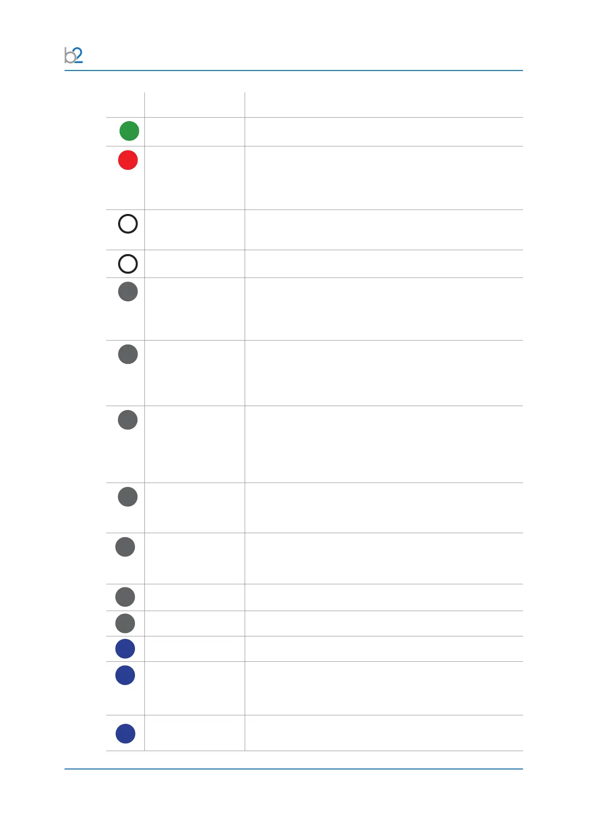
Nr� Name Description
1
Earthing connector Serves as connection point from HVA to earth.
10
HV output connector Serves as connection point from the HVA to the HV test lead.
To connect:
Screw the HV test lead into the HV output connector (until a
click can be heard) and tighten.
30
Power supply plug Serves as connection point from the HVA to the100V-240V,
50/60 Hz power source.
31
Communication port Serves as connection point from the HVA to a USB device.
40
HVswitch[on/o]
button
Activates high voltage.
To activate HV output:
Press within 10 seconds after “Start” - see 5.3 Automatic
Test Mode on page 55
41
Navigation knob Enables user to select options and functions shown on display
- see 5.3 Automatic Test Mode on page 55
- To scroll selection up or down: Rotate
- To enter selection: Click (push in)
42
Emergency OFF
button
Activates emergency shutdown.
Device operation is only possible if the Emergency OFF
button is deactivated.
- To activate Emergency OFF: Press in
- To deactivate Emergency OFF: Release latch and rotate
43
Keyswitch[on/o] Locks the unit to prevent unauthorized use.
- To disable unit: Remove key from the OFF Position
- To reactivate unit: Replace key and turn to ON Position.
47
Remote control
interlock plug
Provides interlock for the remote switch (i.e. interlock). Can
beconnectedtoaremoteemergencyoswitch,agate,foot
pedal or a main switch.
48
Air vent Air inlet for cooling of electronic elements.
49
Air vent Air outlet for cooling of electronic elements.
70
Display screen Displays menu, options and status information.
71
Red LED Indicates HV status. Red light indicates:
- High Voltage is ON (possible DANGER)
- DUT is not discharged (residual voltage > 100 V)
72
Green LED Indicates HV status. Green light indicates:
- High Voltage is OFF