WWW.BALTIMOREAIRCOIL.COM
10
Rigging
Guide
Plenum
Side
Coil
Connections
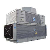
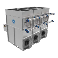
Figure 15. Coil Module End
Figure 14b. Detail of Corner Column
CornerColumn
78”or97”
Length
of“D”Seal
42”Length
of“D”Seal
5/8”Space
Betweenthe
RiggingGuide
and“D”Seal
RiggingGuide
5/8”Space
Betweenthe
RiggingGuide
and“D”Seal
RiggingGuide
(4places)
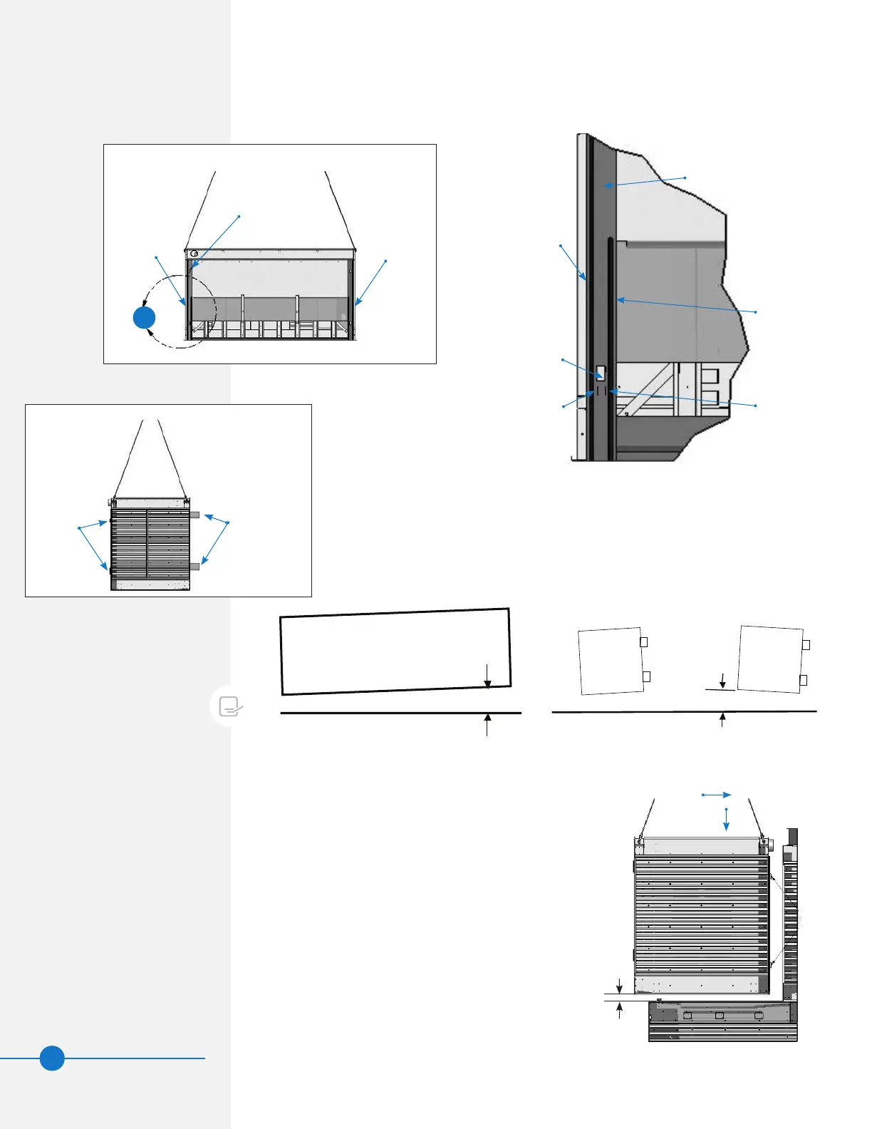
Figure 14a. Coil Module as Seen from the Plenum Side
14b
“D”Seal
“D”Seal
7. Beforeriggingthecoilmodules,wipeanymoistureanddebrisfromthecornercolumns
andapply“D”seals(BACpart#271665)attwolocationsoneachcoilmoduleas
showninFigure 14b.
± 1/2°
X
+1°
-0°
OK
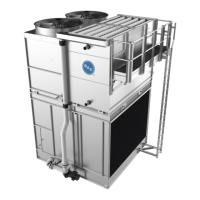
Figure 16. Coil Module Level Tolerance as Seen from the
Plenum Side
Figure 17. Coil Module Level Tolerance as Seen
From the Coil Module End
8. Liftthecoilmoduleandverifythatitislevel.Adjustliftingdevicesas
necessarytolevelthecoilmodulebeforeattemptingtoset.Thecoil
connectionofthecoilmoduleweighsmoreandwillaffectthebalance.
TolerancesaregiveninFigures 16and17.
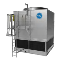
NOTE: Failure to level the
coil module for rigging will prevent
proper engagement of rigging
guides.
9. Toengagetheriggingguides,
thecoilmodulemustbe
positionedbetween23/4”
and33/4”abovethelower
sectionasitismovedtowards
theplenummodule.Oncethe
coilmoduleriggingguideshave
engagedtheplenummodule
cornercolumns,lowerthecoil
intonalpositionasshownin
Figure 18.
10. Boltthecoilmoduletothelower
sectionalongthelouverface
ange.SeeFigure 5on page 5
fortypicalboltingdetails.
Figure 18. Coil Module Rigging
FirstIn
ThenDown
Rigging
Guides
23/4”to33/4”