EPT1 Black (1) Red (2)
FT1 (1/2" OP) Black (1) Black (2)
FT1E Black (1) Green (2)
FT2 White (1) White (2)
FT420 Black (1) White (2)
MSE1 Black (1) Red (2)
MSE5 Black (1) Red (2)
PFT1E Brown (1) Orange (2)
PFT2 White (1) White (2)
PFT2E Black (1) Green (2)
PFT3E Black (1) Green (2)
PFT3W Black (1) Red (2)
PFT420 Black (1) White (2)
PFT420/2 Black (1) White (2)
PFT4E Brown (1) Orange (2)
PM5 Black (1) Red (2)
3
Installation
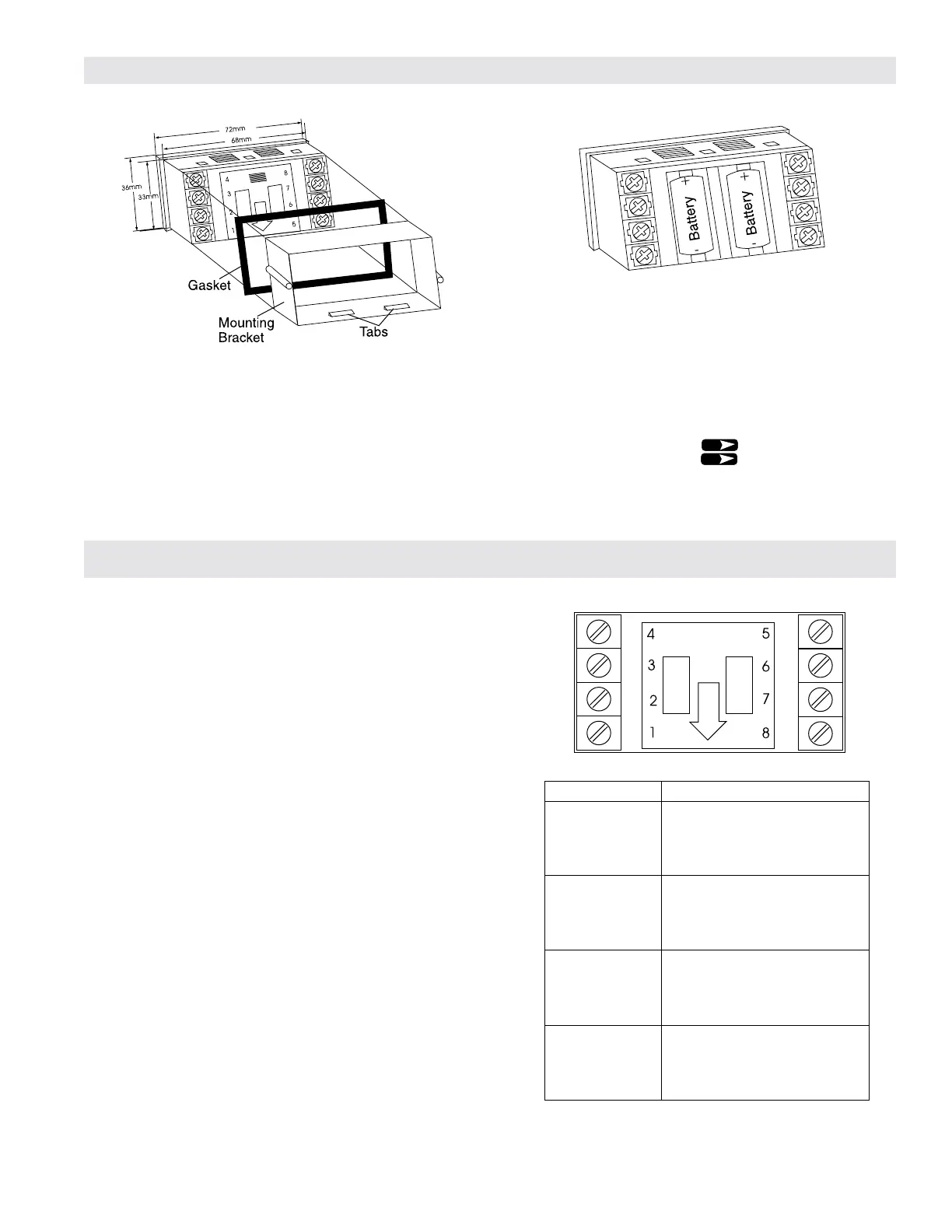
Battery Installation
The ER-9 is shipped with two batteries, which are not installed.
Remove the battery cover by pushing inward and down. Install the
batteries in the two slots. The two batteries are capable of sustaining
the pulse output for 6 months at 50% duty cycle.To extend battery life
to 5 years, utilize an external DC supply for powering the pulse output.
Once the batteries are in place the unit will go into a self test mode, and
all the segments on the LCD display will be illuminated. The self test
mode is exited by depressing the key, which will then display
the model number (9). Depress again to ready the unit for
operation.
1. DC Common
2. Count Input - NPN Signal 280 Hz max. or Dry Contact 95 Hz
max.
3. Not used.
4. Remote Reset - Resets count value when switched to common.
5. Front Panel Program Enable - allows access to program mode
when connected to common.
6. Solid State Relay- Pulse output (+).
7. Solid State Relay- Pulse output ( - )
8. DC Supply Input - 10 to 28 VDC for backlighting and/or powering
the output.
Transmitter Connections
Panel Installation
Place the unit in the panel through a 33mm x 68mm cutout. Slide the
included gasket over the rear of the unit, then slide the panel mount
bracket into place so that the 4 tabs catch in the grooves on the top and
the bottom of the unit (the bracket should be oriented so that the tabs
are on the side nearest the panel). Use the provided panel mount
screws to tighten the bracket until there is a secure seal against the
gasket. Do not over tighten.
TRANSMITTER CONNECTIONS
For connecting to Badger Meter transmitters, refer to the Technical
Brief for your specific transmitter, and the chart to the right. "Connec-
tions" refers to the wires on the transmitter. The numbers in parenthe-
sis refer to the terminal numbers on the ER-9. Connect the wire coming
from the transmitter to the corresponding terminal number on the ER-
9.
To connect a generic reed switch to the ER-9, connect one of the
wires to terminal 1 on the ER-9.
Connect the remaining wire to terminal 2.
To connect a generic NPN transmitter to the ER-9, connect the
emitter to terminal 1 on the ER-9. Connect the collector to terminal 2.
Wiring Instructions
R
R

 Loading...


