Conguring Input/Output (I/O)
S1
S2
1
2
3
4
5
6
7
8
9
A
B
C
Y
G
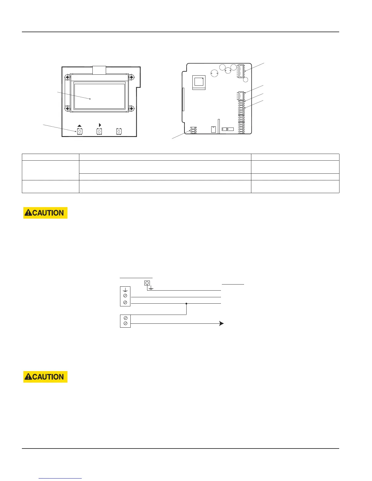
Pulse output, solid-state relays (S1, S2)
Power supply
Coil connector
Display
Push-buttons
Exit
Save
Alarm output (3, 4)
Pulse output, open collector (1, 2)
Figure 18: Configuring I/O
Output Description Terminal
Pulse Output
Open collector max. 10 kHz
Passive max. 32V DC, <100 Hz 100 mA, >100 Hz 20 mA
1 and 2
Solid-state relays max. 230V AC, 500 mA, max. 1 Hz S1 and S2
Alarm Output
Open collector
Passive max. 32V DC, 100 mA
3 and 4
Table 1: Input/output descriptions
• USE SEPARATE CABLE INLETS FOR CABLES CONNECTED TO THE SOLID-STATE RELAY OUTPUT AND CABLES CONNECTED
TO THE OTHER INPUT/OUTPUTS.
• IN MULTIPHASE NETWORKS, SOLID-STATE RELAY SHOULD HANDLE ONLY THE SAME PHASE THAT IS USED FOR
POWERING THEMETER.
Connecting the M7600 Meter to 110V AC from Batch Control Panel Power Supply
Typical concrete batch panel.
S1
S2
Batch Panel
Ground
Neutral
Hot
Meter Pulse Input
Neutral
Hot
Solid-State
Relay Output
Limit 230V AC
Meter
*
Figure 19: Batch panel power connections
• The connection shown in Figure 19 is for batch panels that require a 115V AC hot pulse for meter signals.
• Consult the batch panel manufacturer to confirm the required pulse signal.
• For a 115V AC neutral pulse signal to the batch panel, take the S2 jumper to the 115 neutral power supply.
DO NOT PASS MORE THAN 230V AC THROUGH THE SOLIDSTATE RELAY.
Power Connections
Page 14 February 2018MAG-UM-00507-EN-02

 Loading...


