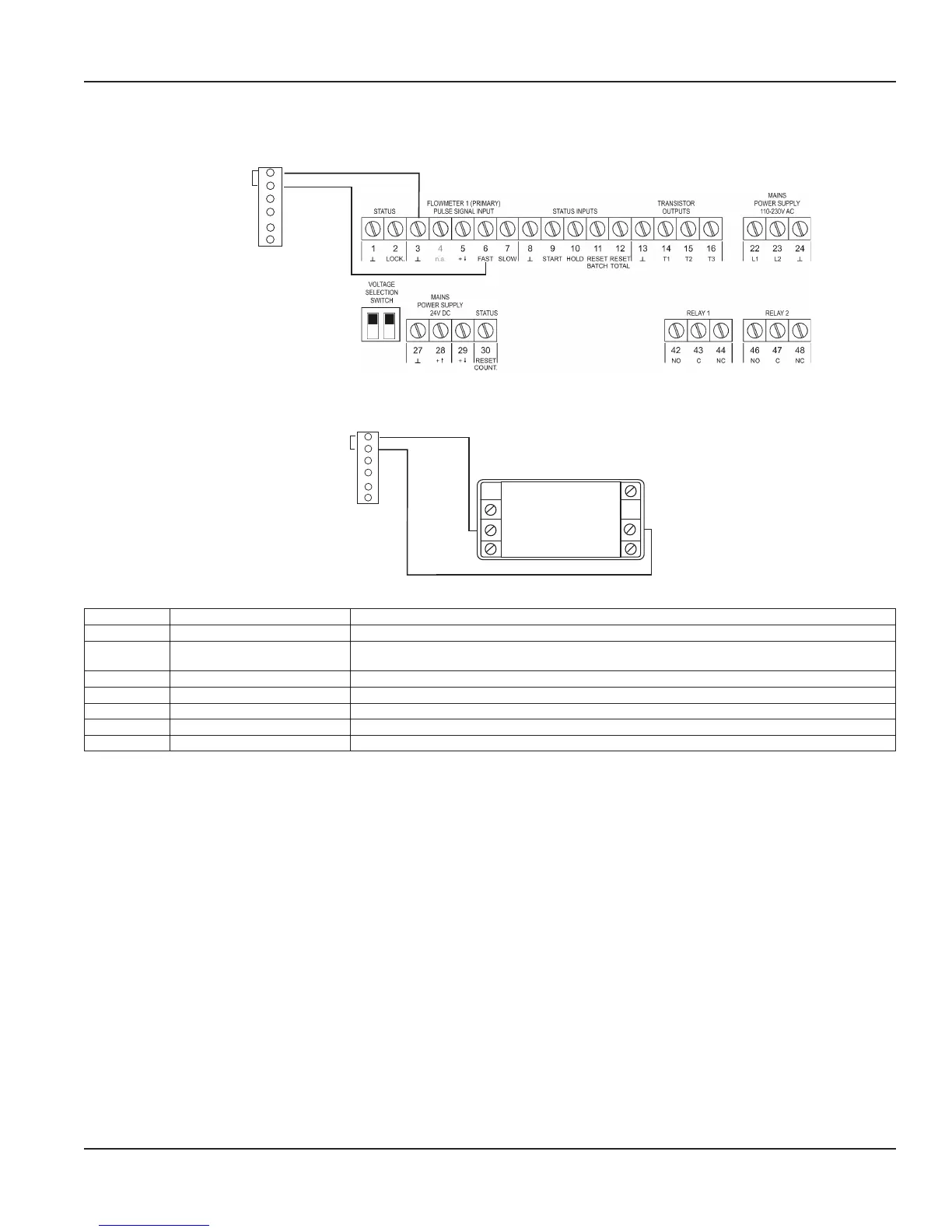
Wiring to a PC-200 Controller
To connect the open collector scaled pulse output from the Model M7600 meter to the PC-200 controller, follow Figure 20.
DC-Switched
Transistor Output
1
2
3
4
5
6
Open Collector
Figure 20: Wiring to a PC-200 controller
Wiring to an ER-10 Industrial Register
5 Enable/R
5 Enable/R
RST 4
IN B 2
GND 1
6 DC Common
7 +10-30VDC7 +10-30VDC
Reset
Count Input
GroundProgram enable
Rear View
DC-Switched
Common
Transistor Output
1
2
3
4
5
6
Open Collector
Figure 21: Wiring to an ER-10 register
Terminal Function Operation
1 Ground —
2 Input B
Count input
Count input
Contact closure of NPN 100 Hz max
3 — Not used
4 Reset Connect to ground to reset totalizer. This is a maintained or level-sensitive reset.
5 Program enable Connect to ground to enter program mode.
6 Backlight common —
7 Backlight power Connect to power to light display.
Table 2: ER-10 wiring terminals
Power Connections
Page 15 February 2018 MAG-UM-00507-EN-02

 Loading...


