BTL5-A/C/E/G1_-M/U_ _ _ _-K-SR 32/K_ _
Micropulse Linear Transducer - Rod Style
3
english
2.1 Characteristics
Micropulse transducers feature:
– Very high resolution, repeatability
and linearity
– Wear- and maintenance-free
– Immunity to shock, vibration, con-
tamination and electrical noise
– An absolute output signal
– Pressure rated to 600 bar
– Protection class per IEC 529:
IP 67 for connector version,
IP 68 (5 bar/48 h) for cable version
2.2 Function
The Micropulse transducer contains
a tubular waveguide enclosed by an
outer stainless steel rod. A magnet
attached to the moving member of
the machine or to the cylinder pis-
ton is moved over the rod and its
position constantly updated.
The magnet defines the measured
position on the waveguide. An inter-
nally generated INIT pulse interacts
with the magnetic field of the mag-
net to generate a magnetostrictive
torsional wave in the waveguide
which propagates at ultrasonic
speed.
The torsional wave arriving at the
end of the waveguide is absorbed in
the damping zone. The wave arriv-
ing at the beginning of the wave-
guide creates an electrical signal in
the coil surrounding the waveguide.
The propagation time of the wave is
used to derive the position. Depend-
ing on the version the corresponding
value is output as a voltage or a cur-
rent either with rising or falling char-
acteristic. This process takes place
with measuring high precision and
repeatability within the stroke range
defined as nominal stroke length.
At the rod end is a damping zone,
within which no reliable signal is
available, but which may be entered
by the magnet.
The electrical connection between
the transducer, the processor/con-
troller and the power supply is via a
cable, which depending on the ver-
sion is either fixed or connected
using a female connector.
2 Function and Characteristics
Dimensions for installing the
Micropulse transducer:
➥➥
➥➥
➥ Fig. 3-2
Dimensions for installing the mag-
net:
➥➥
➥➥
➥ Fig. 3-4
2.3 Available stroke lengths
and magnets
To provide for optimum fit in any
application, a wide range of stan-
dard stroke lengths and magnets in
various form factors are available.
Magnets must therefore be ordered
separately.
The following nominal stroke
lengths are available:
Stroke lengths
[mm]
Increments
[mm]
50 ... 500 25
500 ... 1000 50
1000 ... 2000 100
2000 ... 4000 250
Other stroke lengths on request.
3 Installation
3.1 Mounting
When possible, use non-magnetiz-
able material for attaching the trans-
ducer and magnet ring.
➥➥
➥➥
➥ Fig. 3-1.
When attaching the transducer to
magnetizable materials, appro-
priate measures must be taken to
protect against magnetic disturb-
ances
➥➥
➥➥
➥
Fig. 3-1. Note the
recommended distance of the
transducer and cylinder from
strong, external magnetic fields.
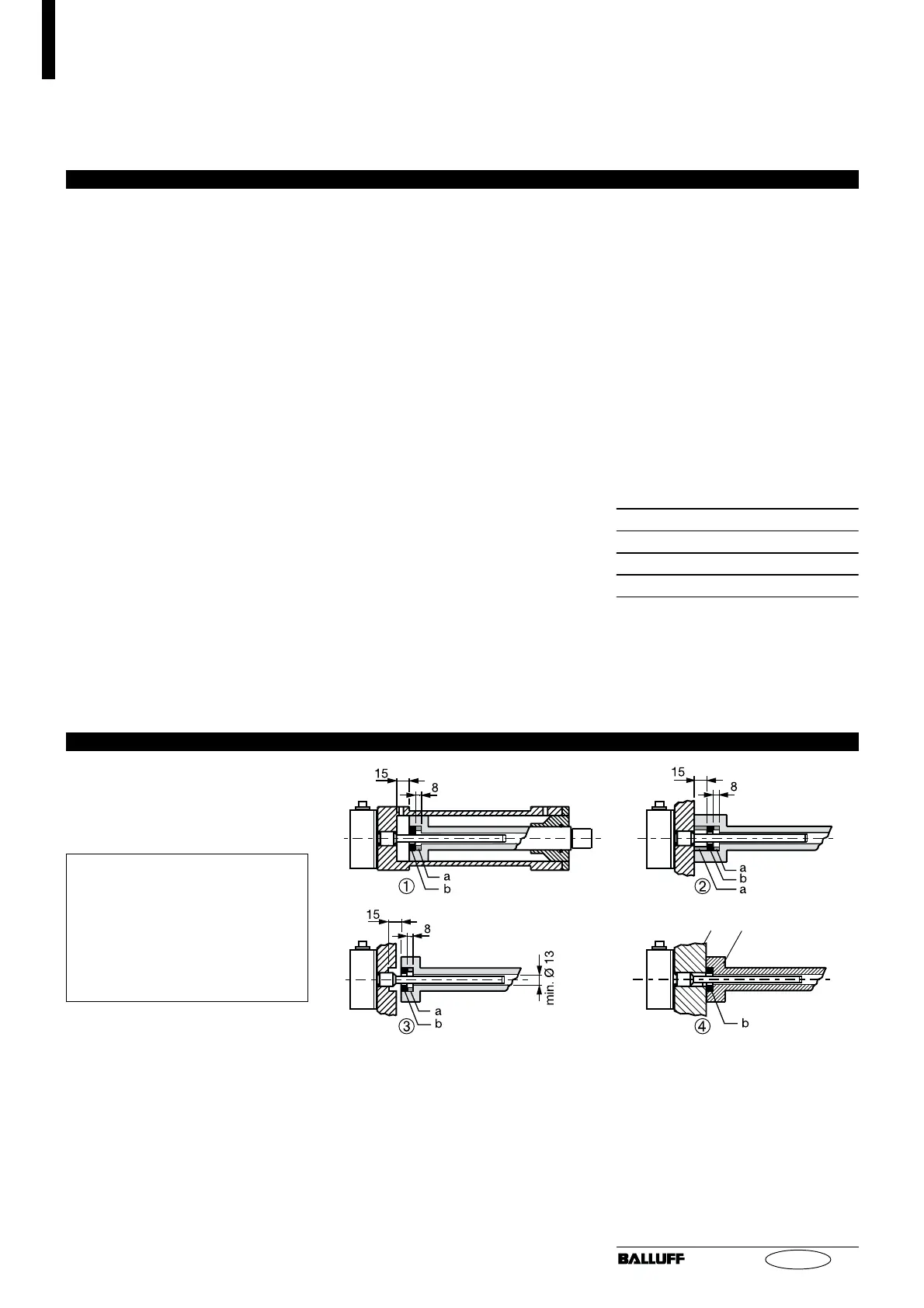
Fig. 3-1: Mounting
➀ - ➂ for magnetizable materials
➃ for non-magnetizable materials
a = Spacer made of non-mag-
netizable materials
b = Magnet
non-magnetizable material