BTL5-A/C/E/G1_-M/U_ _ _ _-K-SR 32/K_ _
Micropulse Linear Transducer - Rod Style
5
english
4 Wiring3 Installation (cont.)
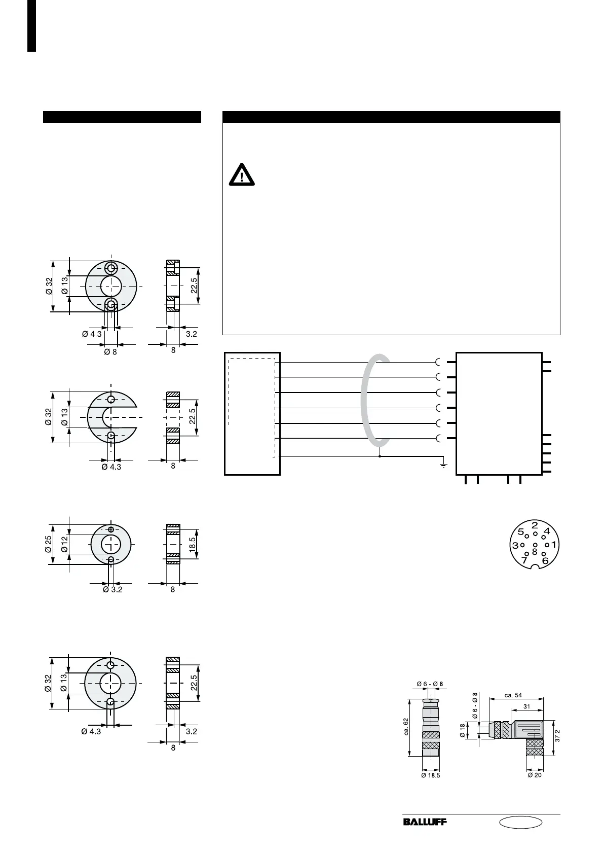
Fig. 3-4: Magnet (optional)
BTL-P-1013-4R
3.3 Magnets, Installation
A magnet is required for each trans-
ducer. This must be ordered sepa-
rately.
➥➥
➥➥
➥ Fig. 3-4.
For mounting the magnet we rec-
ommend to use non-magnetizable
material.
➥➥
➥➥
➥ Fig. 3-1.
BTL-P-1013-4S
BTL-P-1012-4R
Note the following when mak-
ing electrical connections:
System and control cabi-
net must be at the same
ground potential.
To ensure the electromagnetic
compatibility (EMC) which Balluff
warrants with the CE Mark, the
following instructions must be
strictly followed.
BTL transducer and the proces-
sor/control must be connected
using shielded cable.
Shielding: Copper filament
braided, 80% coverage.
When routing the cable between the
transducer, controller and power
supply, avoid proximity to high volt-
age lines to prevent noise coupling.
Especially critical is inductive noise
caused by AC harmonics (e.g. from
phase-control devices), against
which the cable shield provides only
limited protection.
Cable length max. 20 m; Ø 6 to
8 mm. Longer lengths may be used
if construction, shielding and routing
are such that external noise fields
will have no effect on signal integrity.
The shield must be tied to the
connector housing in the BKS
connector (
➥➥
➥➥
➥
Fig. 4-3); see in-
structions accompanying the con-
nector.
In the cable version the cable shield
is connected to the housing in the
PG fitting.
The cable shield must be grounded
on the control side, i.e., connected
to the protection ground.
Pin assignments can be found in
➥➥
➥➥
➥
Table 4-1. Connections on the
controller side may vary according
to the controller and configuration
used.
Fig 3-5: Spacer
straignt
BKS-S 32M-00
No. 99-5672-19-08
(Binder part no.)
right-angle
BKS-S 33M-00
No. 99-5672-78-08
(Binder part no.)
Fig. 4-3: Connector (optional)
Cable entry
(PG 9 fitting)
Fig. 4-1: BTL5-A11...K_ _ with processor/controller, wiring example
BTL5-A11-
...K_ _
YE
GY
PK
GN
BU
BN
not used
0 V
10...0 V
0...10 V
GND
+24 V
processor/
controller with
analog input
Fig. 4-2: Pin assignments BKS,
connector type BTL
BKS connector, view
towards solder side of
female BKS-S 32M-00
or BKS-S 33M-00