BTL5-A/C/E/G1_-M/U_ _ _ _-K-SR 32/K_ _
Micropulse Linear Transducer - Rod Style
7
english
5 Startup (cont.)
5.3 Turning on the system
Note that the system may execute
uncontrolled movements when first
turned on or when the transducer is
part of a closed-loop system whose
parameters have not yet been set.
Therefore make sure that no haz-
ards could result from these situa-
tions.
5.4 Check output values
After replacing or repairing a trans-
ducer, it is advisable to verify the
values for the start and end position
of the magnet in manual mode. If
values other* than those present
before the replacement or repair are
found, a correction should be made.
* Transducers are subject to modifi-
cation or manufacturing tolerances.
5.5 Check functionality
The functionality of the transducer
system and all its associated com-
ponents should be regularly
checked and recorded.
5.6 Fault conditions
When there is evidence that the
transducer system is not operating
properly, it should be taken out of
service and guarded against unau-
thorized use.
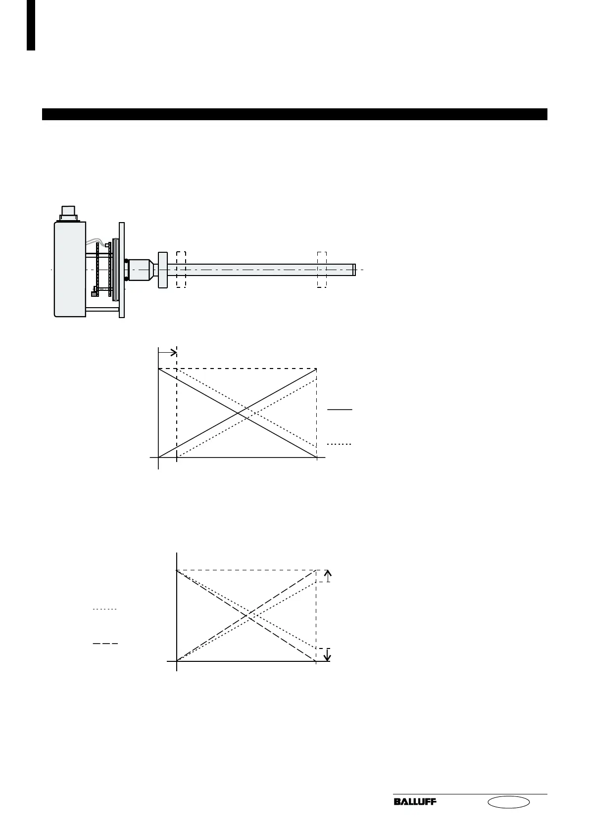
Example: Shift nullpoint out by 15%, no change to endpoint:
Fig. 5-4: Recalibration
Step 6: Replace cover using the original (shorter) M4 x 30 screws, and
tighten using a max. tightening torque of 2.8 Nm.
Caution: Be sure the gasket is seated properly!
Avoid any damage to the O-ring.
before
after
Step 5: Turn "E" pot until the desired end value is read
on the output.
rising
falling
Step 3: Turn "0" pot until the desired start value is read
on the output.
End value:
"E" pot
new nominal stroke 100 %
Step 4: Bring magnet to new endpoint "E".
Start
value:
"0" pot
before
after
Step 2: Bring magnet to new start point "0" .
Step 1: Remove 3 M4 x 30 screws (see Fig. 5-1) and
replace with 3 M4 x 60 screws (not included).
Caution: internal cable connection!
Remove cover carefully (see Fig. 5-2).
"0" "E"