www.balluff.com 11english
4.4.3 Cable connection
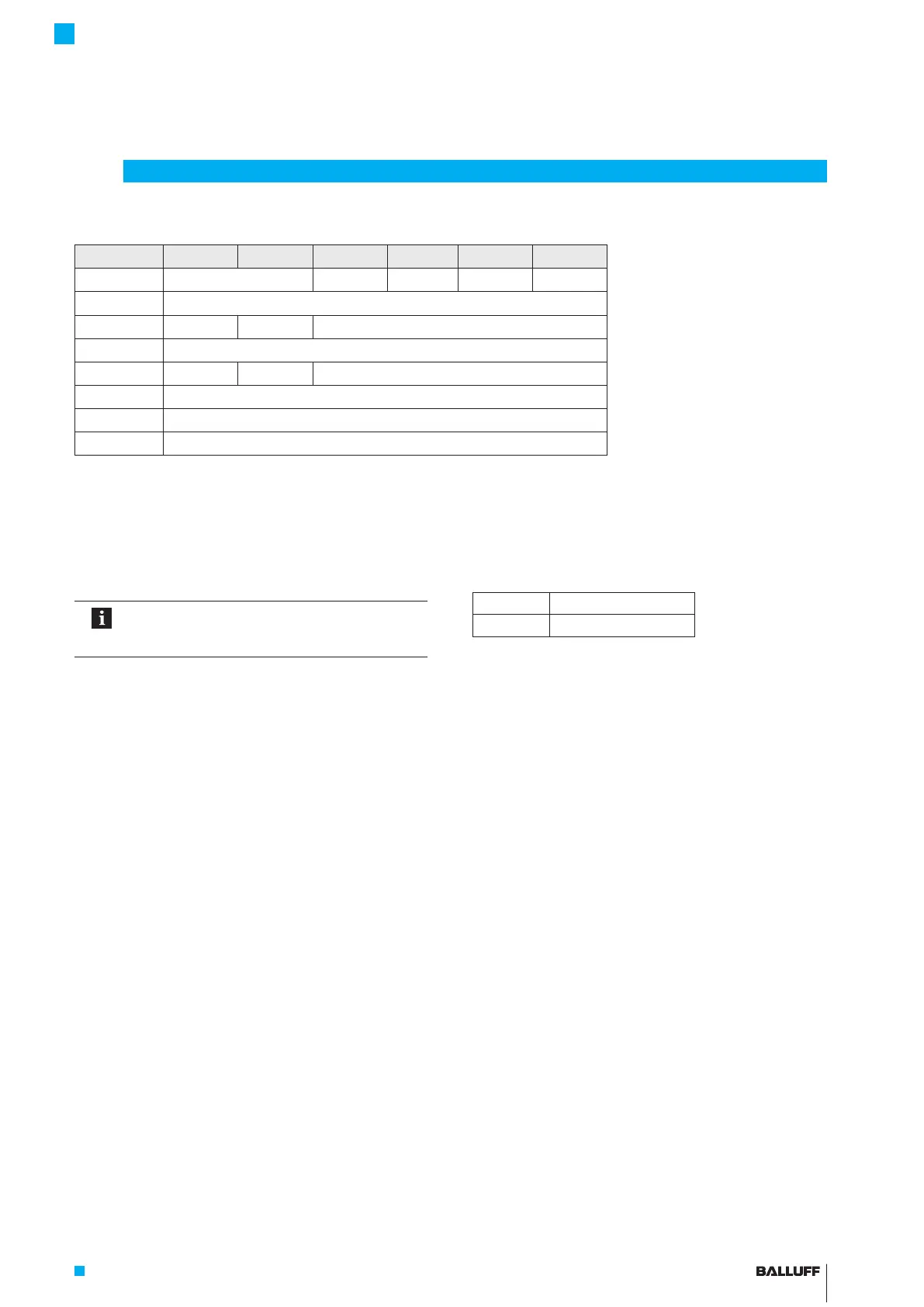
Cable color -A510 -G510 -C500 -C570 -E500 -E570
YE yellow Not used
1)
0…20 mA 20…0 mA 4…20 mA 20…4 mA
GY gray 0 V
PK pink 10…0V 10…–10V 10…0V
3)
RD red La (programming input)
GN green 0…10V –10…10V 0…10V
3)
BU blue GND
2)
BN brown 10…30V
WH white Lb (programming input)
1)
Unassigned leads can be connected to the GND on the controller side but not to the shield.
2)
Reference potential for supply voltage and EMC-GND.
3)
The voltage outputs may exhibit a minimal offset to the harmonized current output.
Tab. 4-4: Cable assignment BTL7… cable
4.5 Shielding and cable routing
Defined ground!
The transducer and the control cabinet must be
at the same ground potential.
Shielding
To ensure electromagnetic compatibility (EMC), observe
the following:
– Connect transducer and controller using a shielded
cable.
Shielding: Braided copper shield with minimum 85%.
– Connector version: Shield is internally connected to
connector housing.
– Cable version: On the transducer side, the cable
shielding is connected to the housing.
Ground the cable shielding on the controller side
(connect with the protective earth conductor).
Magnetic fields
The linear encoder is a magnetostrictive system. It is
important to maintain adequate distance between the
transducer/holding cylinder and strong, external magnetic
fields.
Cable routing
Do not route the cable between the transducer, controller,
and power supply near high voltage cables (inductive stray
noise is possible).
The cable must be routed tension-free.
Bending radius for fixed cable
The bending radius for a fixed cable must be at least five
times the cable diameter.
4
Installation and connection (continued)
Cable length
BTL7-A/G Max. 30 m
1)
BTL7-C/E Max. 100 m
1)
1)
Prerequisite: Construction, shielding and routing preclude the effect of any
external noise fields.
Tab. 4-5: Cable lengths BTL7
BTL7-A/C/E/G5 __ -M ____ -K(8)-SR32/SR115/___
Micropulse Transducer - Rod Style

 Loading...


