www.balluff.com 13english
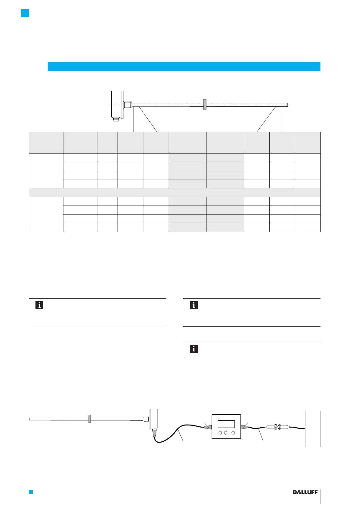
Output
gradient
Linear
transducer
Unit Min.
value
Null
value
Indication
for
adjustment
Indication
for teach-in
End
value
Max.
value
Error
value
Rising BTL7-A… V −0.5 0 2.0 4.0 +10.0 +10.5 +10.5
BTL7-G… V −10.5 −10.0 2.0 4.0 +10.0 +10.5 +10.5
BTL7-C… mA 0 0 6.0 12.0 20.0 20.4 20.4
BTL7-E… mA 3.6 4.0 6.0 12.0 20.0 20.4 3.6
Falling BTL7-A… V +10.5 +10.0 2.0 4.0 0 −0.5 −0.5
BTL7-G… V +10.5 +10.0 2.0 4.0 −10.0 −10.5 −10.5
BTL7-C… mA 20.4 20.0 6.0 12.0 0 0 20.4
BTL7-E… mA 20.4 20.0 6.0 12.0 4.0 3.6 3.6
Tab. 6-1: Value table for teach-in and inverting
6.1 Programming inputs
Programming inputs La and Lb must be used in order to
make settings. A programming input at 10 to 30V
corresponds to activation (high active).
The Balluff BTL7-A-CB02-… adjusting box can be used for
this (see Accessories on page22).
Automatic deactivation!
If no signals are transmitted via the
programming inputs for approx.10min,
programming mode is automatically ended.
6.2 Calibration procedure notes
Prerequisites
– Programming inputs are connected.
– The transducer is connected to the system controller.
– Voltage or current values from the transducer can be
read (using a multimeter, the system control or the
adjusting box).
Fig. 6-1: Connecting the BTL7-A-CB02-S… adjusting box
6
Calibration procedure
Values for null and end point
– Any desired position of the magnet can be used as the
null or end point. However, the null and end points may
not be reversed.
– The absolute null and end points must lie within the
minimum or maximum range of what can be output
(see value table).
The last set values are always saved, regardless
of whether the setting was ended using the
programming inputs or automatically after
10min have expired.
Value table for teach-in and inverting
The following examples refer to transducers
with 0 to 10 V or 4 to 20 mA output.
Transducer
Calibration box
Supply
Adapter cable with connector
(socket)
Adapter cable with
connector (luster terminal)
6-pin8-pin
BTL7-A/C/E/G5 __ -M ____ -K(8)-SR32/SR115/___
Micropulse Transducer - Rod Style

 Loading...


