10 english
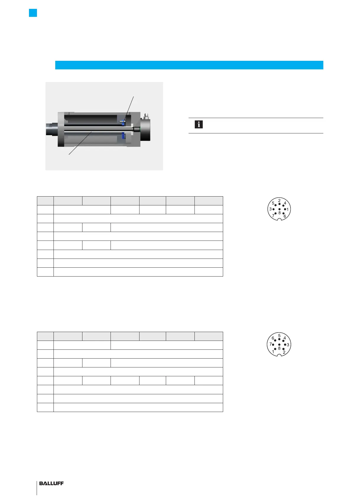
Fig. 4-7:
Magnet
(e.g. BTL-P-1028-15R)
Supporting rod made of non-magnetizable material
Example2, transducer installed with supporting rod
4.4 Electrical connection
Depending on the model, the electrical connection is made
using a cable or a connector (BTL7…-SR32, BTL7…-SR115).
The connection or pin assignments for the respective version
can be found in Tab. 4-2 to Tab. 4-4.
Note the information on shielding and cable
routing on page11.
4
Installation and connection (continued)
4.4.1 Connector SR32
Pin -A510 -G510 -C500 -C570 -E500 -E570
Fig. 4-8: Pin assignment of SR32 (view
from above on transducer), 8-pin
M16 circular plug
1 Not used
1)
0…20 mA 20…0 mA 4…20 mA 20…4 mA
2 0 V
3 10…0V 10…–10V 10…0V
3)
4 La (programming input)
5 0…10V –10…10V 0…10V
3)
6 GND
2)
7 10…30V
8 Lb (programming input)
1)
Unassigned leads can be connected to the GND on the controller side but not to the shield.
2)
Reference potential for supply voltage and EMC-GND.
3)
The voltage outputs may exhibit a minimal offset to the harmonized current output.
Tab. 4-2: Connection assignment BTL7…-SR32
4.4.2 Connector SR115
Pin -A510 -G510 -C500 -C570 -E500 -E570
Fig. 4-9: Pin assignment of SR115 (view
from above on transducer), 8-pin
M12 circular plug
1 0 V (pin 3) Not used
1)
2 0 V (pin 5)
3 10…0V 10…–10V Not used
1)
4 La (programming input)
5 0…10V –10…10V 0…20 mA 20…0 mA 4…20 mA 20…4 mA
6 GND
2)
7 10…30V
8 Lb (programming input)
1)
Unassigned leads can be connected to the GND on the controller side but not to the shield.
2)
Reference potential for supply voltage and EMC-GND.
Tab. 4-3: Connection assignment BTL7…-SR115
BTL7-A/C/E/G5 __ -M ____ -K(8)-SR32/SR115/___
Micropulse Transducer - Rod Style

 Loading...


