14 english
6.3 Calibration procedure overview
6.3.1 Teach-in
The factory set null point and end point is replaced by a
new null point and end point. The null point and end point
can be set separately, the output gradient changes.
The detailed procedure for teach-in is described
on page16.
Steps:
► Move magnet to the new null position.
► Read new null point by activating the programming
inputs.
⇒ The current end point remains the same.
New null point
Before
After
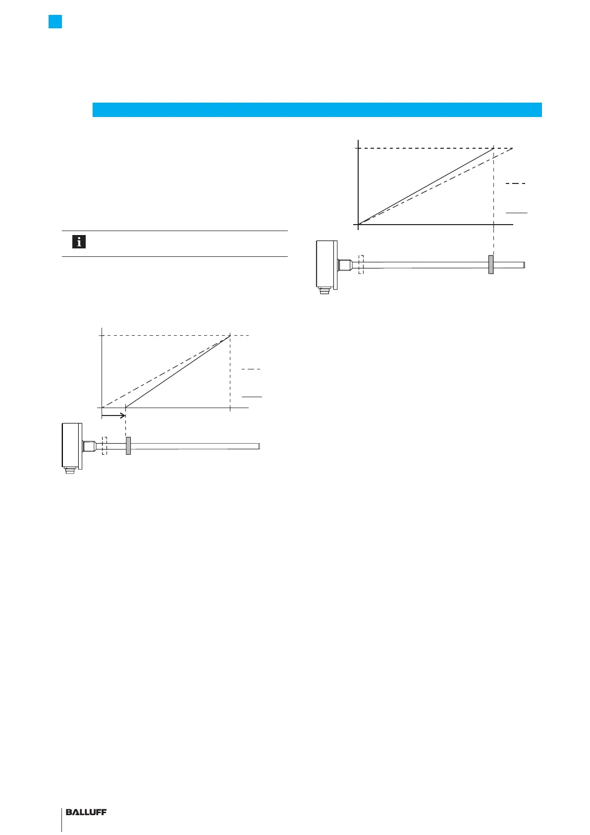
Fig. 6-2: Reading new null point
► Move magnet to the new end position.
► Read new end point by activating the programming
inputs.
⇒ The current null point remains the same.
6
Calibration procedure (continued)
New end point
Before
After
Fig. 6-3: Reading new end point
Only with BTL7-C/E…:
► The gradient of the current output can be inverted by
activating the programming inputs.
⇒ For example, a rising output gradient is changed to
a falling gradient. The voltage outputs are not
inverted.
BTL7-A/C/E/G5 __ -M ____ -K(8)-SR32/SR115/___
Micropulse Transducer - Rod Style

 Loading...


