Manual Documentation Number M3640D1598 25
B&B Electronics -- PO Box 1040 -- Ottawa, IL 61350
PH (815) 433-5100 -- FAX (815) 433-5104
Notes:
• Insert the base, collector, and emitter pins into the correct sockets.
• Some power Darlington transistors contain internal base-to-emitter
resistors. Because the meter uses two current readings to calculate hFE,
any internal transistor resistance causes undependable readings.
• Do not take the hFE reading as an absolute measurement, but rather as
an indication that the transistor is operation. The true gain of a transistor
depends on its operating current. This meter applies up to 1000 uA to
the emitter and collector and measures the collector current to calculate
the hFE.
• You can’t measure the hFE of a transistor that is connected in a circuit.
• You cannot measure the hFE of a FET or other non-bipolar transistor.
• High-voltage junctions in power transistors prevent correct readings.
Also, the larger leads of the power transistor can damage the test socket.
• Do not try to determine type, pin-out, or hFE for power transistors with
this meter.
• hFE is affected by temperature. Try not to warm the transistor with your
hand when you instalI the device in the socket. If the hFE reading is not
stable when you first measure it, let the transistor’s temperature
stabilize.
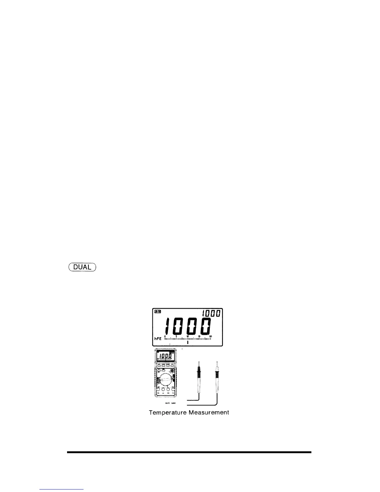
6-10. Measuring Temperature (M-3640D / 3660D only)
The meter can directly display the temperature with dual-display by
reading Celsius in the main-display and Fahrenheit on the sub-display at
mode.
Temperature from -40°C to 1200°C can be measured by using optional
K-type thermocouple at TEMP position.