26 Manual Documentation Number M3640D1598
B&B Electronics -- PO Box 1040 -- Ottawa, IL 61350
PH (815) 433-5100 -- FAX (815) 433-5104
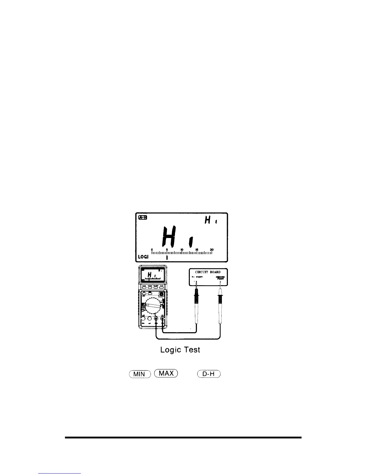
6-11. Logic Test
The logic function lets you easily check digital circuits to determine the
logic state of different parts of the circuit. Rather than display an absolute
voltage, this function displays Hi, LO, or ••• indicate logic high, low, or
undetermined respectively.
Follow these steps to perform a logic test:
1. Rotate the rotary switch to the HIGH/LOW range.
2. Plug the test leads into the COM and V/Ω inputs.
3. Connect the black probe to the ground point (GND) of the test circuit
and the red probe to the supplying voltage point (V+). While keeping
the test probes firmly connected to each point, press SET/RESET
button.
4. While keeping a connection between the black probe and the circuits
GND point, move the red probe to the other desired points. The meter
immediately displays one of the 3 modes, as follows:
• If value exceeds above 70% of the stored value, the Hi (HIGH)
appears.
• If value falls below 30% of the stored value Lo (LOW) appears.
• If value is between stored reference value, ••• segment appears.
Notes:
• In this mode, the
and functions do not work.
• To set the reference value, the supplying voltage should be 3V or more,
The testing range of logic is limited from 0V up to 19.99V