Fiber Outer Diameter (mm) Adapter Color
Ø 1.0 Black
Ø 1.3 Red
Ø 2.2 No adapter needed
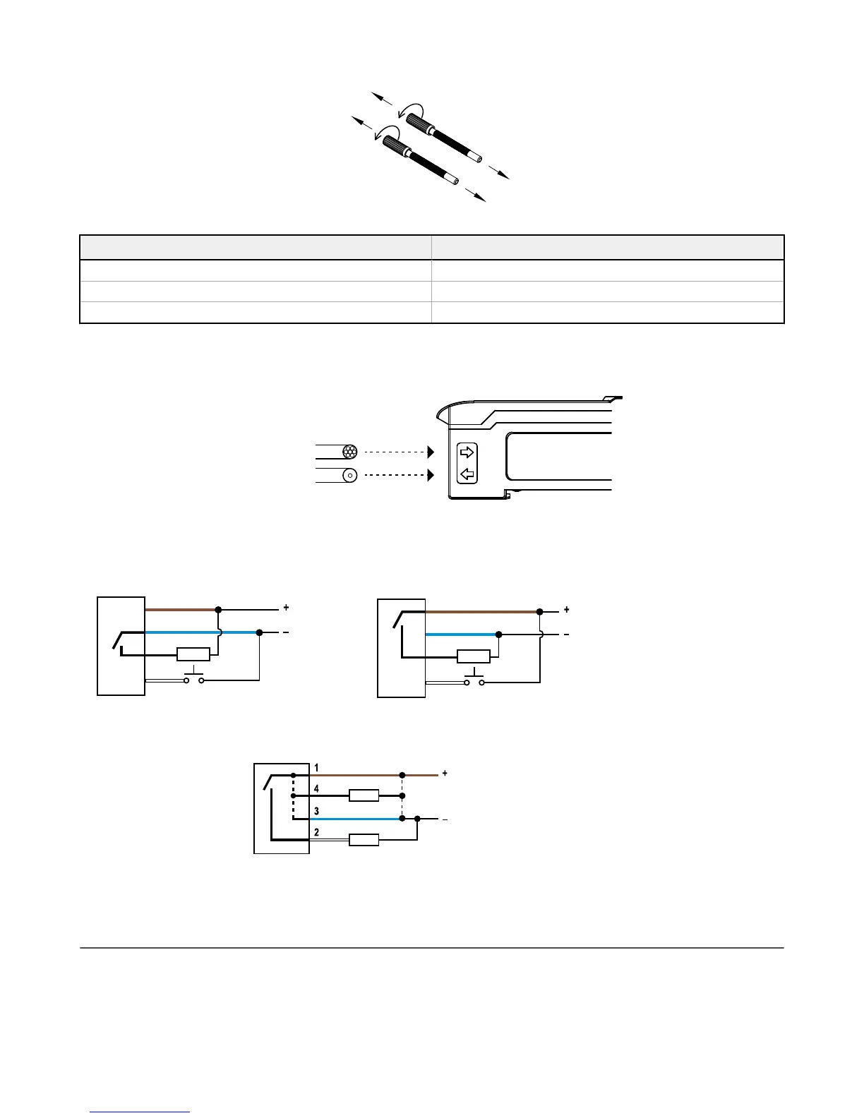
When connecting coaxial-type fiber assemblies to the amplifier, install the single-core (center) fiber to the Transmitter port, and the
multi-core (outer) fiber to the Receiver port. This will result in the most reliable detection.
TRANSMITTER
RECEIVER
Single-core fiber
Multi-core fiber
Wiring Diagrams
NPN Models
Load
10-30V dc
Remote
Programming
(N.O.)
1
3
4
2
PNP Models
Load
10-30V dc
Remote
Programming
(N.O.)
1
3
4
2
Key
1 = Brown
2 = White
3 = Blue
4 = Black
IO-Link Models
PUSH-PULL
18–30 V dc
Load
Load
Open lead wires must be
connected to a terminal
block.
Top Panel Interface
Opening the dust cover provides access to the top panel interface. The top panel interface consists of the RUN/PRG/ADJ mode
switch, LO/DO switch, +/SET/- rocker button, dual red/green digital displays, and output LED.
DF-G1 Expert
™
Dual Display Fiber Amplifier
P/N 161275 Rev. E www.bannerengineering.com - Tel: + 1 888 373 6767 3
 Loading...