Quick Start Guide
Class 1 laser CMOS sensor with dual outputs and IO-Link. Patent pending.
This guide is designed to help you set up and install the Q4X Sensor with Dual Discrete Outputs and IO-Link. For complete information on
programming, performance, troubleshooting, dimensions, and accessories, please refer to the Instruction Manual at www.bannerengineering.com.
Search for p/n 190074 to view the Instruction Manual. Use of this document assumes familiarity with pertinent industry standards and practices.
For illustration purposes, the threaded barrel model Q4X images are used throughout this document.
WARNING:
• Do not use this device for personnel protection
•
Using this device for personnel protection could result in serious injury or death.
• This device does not include the self-checking redundant circuitry necessary to allow its use in personnel safety
applications. A device failure or malfunction can cause either an energized (on) or de-energized (off) output condition.
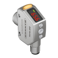
Features
Figure 1. Sensor Features—Threaded Barrel Models
1. Output Indicator (Amber)
2.
Display
3. Buttons
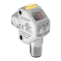
Figure 2. Sensor Features—Flush Mount Models
Display and Indicators
The display is a 4-digit, 7-segment LED. The main screen is the Run mode screen.
For 2-pt, BGS, FGS, and DYN TEACH modes, the display shows the current distance to the target in millimeters. For dual TEACH mode, the display
shows the percentage matched to the taught reference surface. A display value of
indicates the sensor has not been taught.
Figure 3. Display in Run Mode
1. Stability Indicator (STB—Green)
2.
Active TEACH Indicators
• DYN—Dynamic (Amber)
• FGS—Foreground Suppression (Amber)
• BGS—Background Suppression (Amber)
Note: The indicators represent the currently selected channel. However, if Output 2 is set to something other than LO, DO, or
Complementary, then the indicators represent the Channel 1 status.
Output Indicator
•
On—Output is on
• Off—Output is off
Stability Indicator (STB)
• On—Stable signal within the specified sensing range
•
Flashing—Marginal signal, the target is outside the limits of the
specified sensing range, or a multiple peak condition exists
•
Off—No target detected within the specified
sensing range
Active TEACH Indicators (DYN, FGS, and BGS)
•
DYN, FGS, and BGS all off—Two-point TEACH mode selected
(default)
• DYN on—Dynamic TEACH mode selected
• FGS on—Foreground suppression TEACH mode selected
• BGS on—Background suppression TEACH mode selected
• DYN, FGS, and BGS all on—Dual TEACH mode selected
Buttons
Use the sensor buttons (SELECT)(TEACH), (+)(CH1/CH2), and (-)(MODE) to program the sensor.
Q4X Stainless Steel Laser Sensor with Dual
Discrete Outputs and IO-Link
Original Document
190073 Rev. G
18 April 2022