See the following
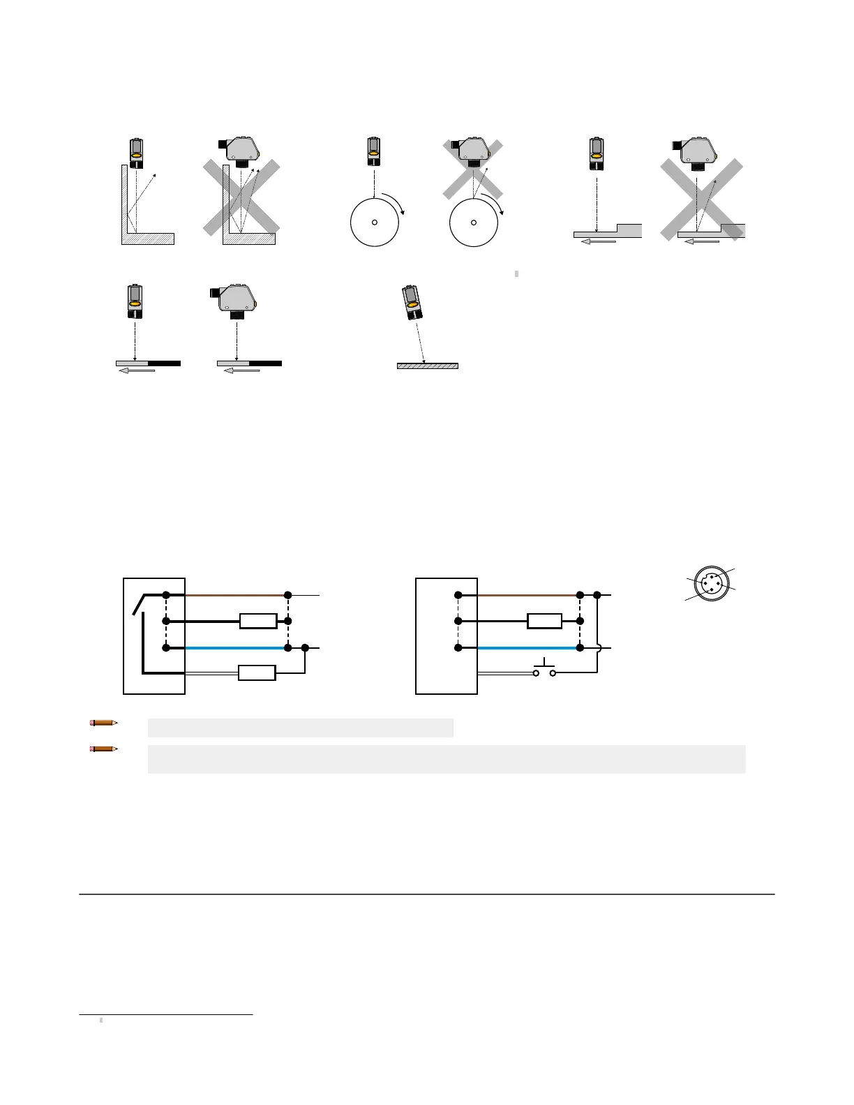
figures for examples of correct and incorrect sensor-to-target orientation as certain placements may pose problems for sensing
some targets. The Q4X can be used in the less preferred orientation and provide reliable detection performance; refer to the
Performance Curves
for
the minimum object separation distance required for each case.
Figure 6. Orientation by a wall
Figure 7. Orientation for a turning object
Figure 8. Orientation for a height difference
Figure 9. Orientation for a color or luster difference
Horizontal
Orientation
Vertical
Orientation
(Optimal)
Figure 10. Orientation for highly reflective target
1
Reflective
Surface
(optional)
Mount the Device
1.
If a bracket is needed, mount the device onto the bracket.
2. Mount the device (or the device and the bracket) to the machine or equipment at the desired location. Do not tighten the mounting screws at
this time.
3. Check the device alignment.
4. Tighten the mounting screws to secure the device (or the device and the bracket) in the aligned position.
Wiring Diagram
Figure 11. Channel 2 as PNP discrete or PFM output
bk (4)
bn (1)
bu (3)
wh (2)
10-30 V DC
CH1
CH2
+
–
PUSH-PULL
Load
Load
Figure 12. Channel 2 as remote input
bk (4)
bn (1)
bu (3)
wh (2)
10–30 V DC
CH1
CH2
+
–
PUSH-PULL
Load
Remote
Input
Key
1 = Brown
2 = White
3 = Blue
4 = Black
Note: Open lead wires must be connected to a terminal block.
Note: The Channel 2 wire function is user-selectable. The default for the wire is PNP output. See the Instruction Manual for
details regarding use as remote input or PFM output.
Cleaning and Maintenance
Clean the sensor when soiled and use with care.
Handle the sensor with care during installation and operation. Sensor windows soiled by fingerprints, dust, water, oil, etc. may create stray light that
may degrade the peak performance of the sensor. Blow the window clear using filtered, compressed air, then clean as necessary using only water
and a lint-free cloth.
Sensor Programming
Program the sensor using the buttons on the sensor or the remote input (limited programming options).
In addition to programming the sensor, use the remote input to disable the buttons for security, preventing unauthorized or accidental programming
changes. See the Instruction Manual, p/n 190074 for more information.
1
Applying tilt to sensor may improve performance on reflective targets. The direction and magnitude of the tilt depends on the application, but a 15° tilt is often sufficient.
Q4X Stainless Steel Laser Sensor with Dual Discrete Outputs and IO-Link
P/N 190073 Rev. G www.bannerengineering.com - Tel: + 1 888 373 6767 3

 Loading...