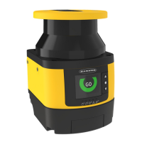
Shut Off Status—Enables or disables the Shut Off function (not available in the SX5-B model). This is an energy savings
feature that tells the scanner to go into sleep mode (display turns off and motor stops). Zone Set 1 becomes Shut Off. This
Zone Set cannot have any Safety or Warning Zones, and the Encoder speed range is set to 0. Coming out of shut off mode
can take about 30 seconds.
Encoder Status—Enables or disables encoders for dynamic applications. This field is only available in scanners that support
encoders (SX5-ME70 with connector 17+8 selected).
These next few fields are only visible (required) if Encoder Status in enabled.
Area Switch Number—Sets the number of Area Switch inputs that are required. This number does not have to match the
Zone Set number because the encoder inputs can be used in conjunction with the area switch inputs to select the Zone Set.
This number can be increased or decreased.
Active Input Number—Sets the number of available Active Inputs. This value can be increased according to the number of
Area Switches.
Encoder Δ (%)—Allowable variation in the speed measures collected by Encoder 1 and Encoder 2. The minimum value is
0%, the maximum value is 45%, and the default value is 25%.
Encoder 1 ÷ 2 (p/cm) - Encoder (1 and 2) pulse number per centimeter. For both encoders, the minimum value is 50 (also
the default value) and the maximum value is 1,000. This value is based on the number of pulses the encoder supplies per
revolution and on the ratio between the vehicles wheel and the friction wheel on which the encoder is mounted.
X ICON (Delete)—Removes selected Zone Set(s); if Zone Set is selected, the Zone Set will be deleted when the 'X'
icon is clicked. This results in the Zone Set Number being reduced by the number of Zone Sets that were just deleted.
Clicking the down arrow of the Zone Set Number also reduces the number of Zone Sets but it will delete the highest
numbered Zone Set (which might not be the Zone Set that needed to be removed).
BINARY ICON (Binary)—Automatically sets the input switch coding. Alternately, you can click the Area Switch boxes
to manually change its state. All Area Switching must differ by two input bit states (or encoder states) to be valid.
CHECK ICON— Validates the Zone Set coding.
If a different input switch coding is configured for each Area Switch, the relevant Zone Sets can have either overlapping or
different encoder Speed Ranges. In this case, all Area Switches must differ by two input bit states to be valid. If more Area
Switches share the same input switch coding, different Speed Ranges must be configured for each Zone Set.
More than one Zone Set can be configured to define either separate or overlapping areas and these can be switched
between using combinations of input signals.
To create a Zone Set, the user must configure it through the scanner's configuration software.
Single Zone Set Configuration
This configuration step allows the user to set the Zone Set parameters.
For this example, the configuration includes only one Zone Set, so it is not necessary to insert or edit any parameters. The
Input Wires parameters do not require any assignments in this situation.
Click the white > to move to the next page.
Multiple Zone Sets Configuration
When more than one Zone Set is used, the Zone Set inputs (area switch inputs) are used to select which Zone Set is active.
External logic (e.g., a PLC) is capable of selecting one of up to 70 (depending on the model) configured Zone Sets stored in
the scanner at any given time.
After the scanner is configured, switching over to or activating an individual Zone Set is controlled by the input pins (area
switch inputs) assigned in the configuration software. The Zone Set selection can also be controlled by the Area Switch
inputs and Encoder input values.
The input combination that makes the Zone Sets change (area switch inputs) must be unique and must not be susceptible to
false external signals (at least two inputs must change).
WARNING:
• Use Zone Set switching to change the area of safeguarding.
•
Failure to follow these instructions could result in serious injury or death.
• Changing the Safety/Warning Zone Set from one pair to another must not expose any
individual to a hazard or hazardous situation. Supplemental safeguarding may be required.
SX Safety Laser Scanner
www.bannerengineering.com - Tel: + 1 888 373 6767 83

 Loading...