2. Introduction to CS-100
2.2 About the Base Un it
Base U nit functionality
The Base Unit receives the wireless input from the B uttons and controls the con tent of the m eeting room display and the sound of
the meeting room’s audio system.
The Base Unit can be inside a cabinet in the meeting room, or put on the meeting room table or mounted on a wall. Check the
Installation Guide for instructions on how to install the Bas e U nit.
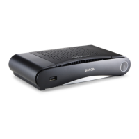
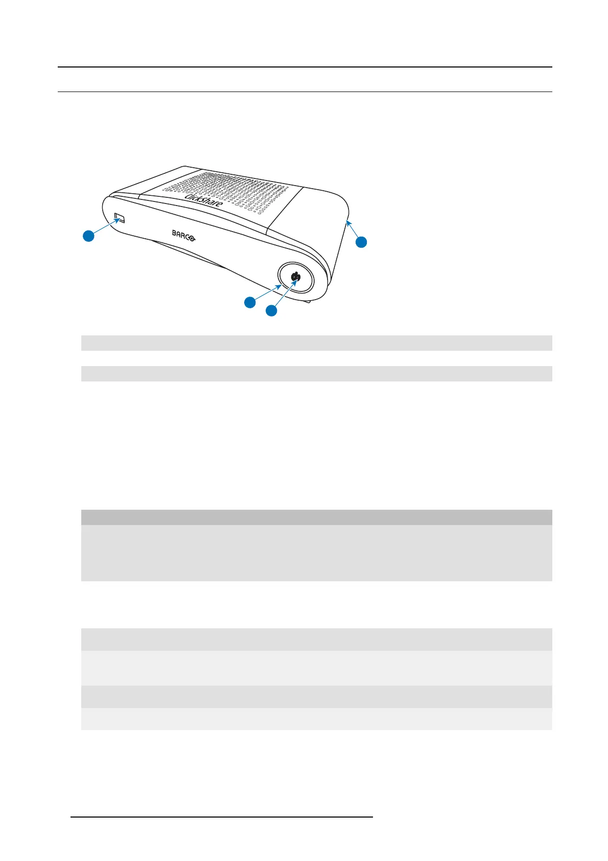
2
1
4
3
Image 2-2
1
USB port
2
Status LED ring
3
Standby Button
4 Kensington lock
Tab l e 2 -3
USB Port
The USB port is used to update the software of both the Base Unit and the B uttons.
When plugging in the Button into the Ba se Unit, the Button is paired to the Bas e Unit. The Base Unit checks whether the software
and firmware of the Button is up to date. If not, the Base Unit updates the software and/or firm ware .
Status LED ring
The color of the LED ring around the pow er button o f the Base Unit gives inform ation on the status of the system.
LEDs behavior Explanation
static r e d
• receiving content from the Buttons and streaming towards the display.
• pairing and software update of the Button is done. You can now unplug the
Button from the B ase Un it.
• during the first phase of the Base Unit boot process.
blinking white
• system is starting up (during th e second phase)
• Button pairing is in progress
• software update of the Base Unit
breathing white
• ECO standby mode
static whit e
• awake and ready (i.e. showing the welcome message on the display)
• pairing is done
red b linking
• an error occurre d
dark
• deep standby/off
Standby button
The button a t the front of the Base Unit has a standby function once the Base unit is powered.
• When the system is in normal oper ational mode, a push makes the system goes into a pre-defined standby m ode.
• When the system is in standby, a push triggers the system to start up and to go into n ormal operational m ode.
6
R5900024 CLICKSHARE CS-100 19/03/2018
 Loading...