Manual 2100-317J
Page 4 of 39
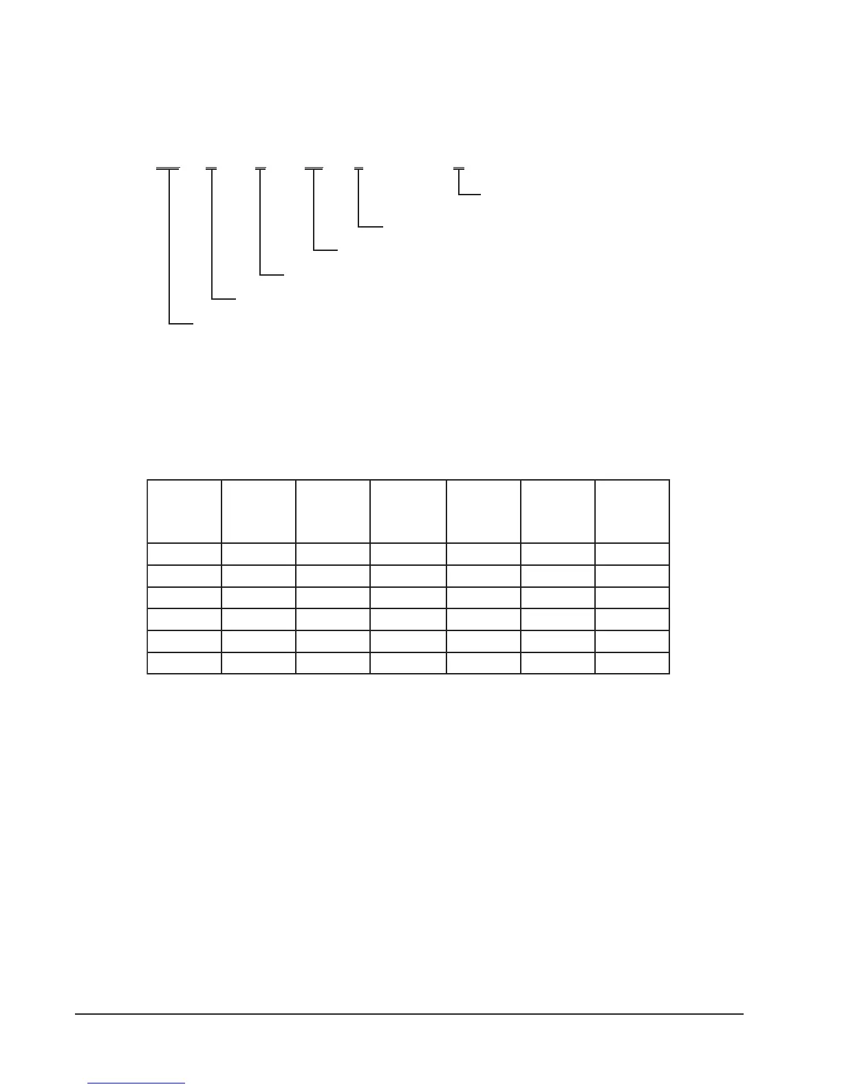
WATER SOURCE PRODUCT LINE NOMENCLATURE
TABLE 1
1
INDOOR BLOWER PERFORMANCE (RATED CFM)
LEDOM
detaR
PSE
XAM
PSE
2
suounitnoC
wolfriA
3
detaR
gnilooC
MFC
4
detaR
gnitaeH
MFC
cirtcelE
taeH
MFC
242SVSG01.006.00050080080001
203SVSG51.006.0055000100010001
163SVSG51.006.0526002100210521
124SVSG02.006.0576052105210521
184SVSG02.006.0008004100410091
106SVSG02.006.0009006100610091
1 Motor will deliver consistent CFM through voltage supply range with no deterioration
(197-253V for all 230/208V models).
2 Continuous CFM is the total air being circulated during continuous (manual fan) mode.
3 Will occur automatically with a call for “Y” for cooling mode operation.
4 Will occur automatically with a call for “W1” for heating mode operation.
EXCEPTION: The rated CFM maybe adjusted +/- 15%, see Table 8. The CFM light on the Blower Control
Board can also be used to “count” the CFM of delivered air, see section on CFM light.
GS V S 36 1- A
Approximate Capacity Size On High Speed
S = Single Capacity Compressor
Electrical Characteristics
A = 230/208-60-1
Modification Code
V = Vertical
Ground Source Heat Pump