Manual 2100-705B
Page 25 of 43
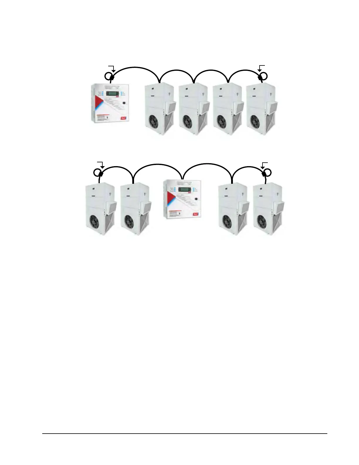
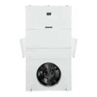
FIGURE 22
Placement of Communication Wire Filters (Daisy Chain and Alternate Methods)
* LC6000 can be in any position other than start and end
with filters placed on end units.
NOTE: Line filters can be on either the unit or controller, whichever device is on the end of the chain. No matter
how many units there are, the two end devices will only have ONE communication cable, whereas the
center devices will all have TWO (as shown above). Maximum two wires in each terminal. Filters go inside
the unit or controller; shown out of unit above for identification only.
Unit 1 Unit 2 Unit 3 Unit 4...up to 14 units
Daisy Chain Wiring
Place filter here
(end unit)
LC6000
Place filter here
LC6000*
Unit 1
Unit 2 Unit 3
Place filter here
(end unit)
Alternate Wiring
Place filter here
(end unit)
Unit 4...up to 14 units