Manual 2100-705B
Page 26 of 43
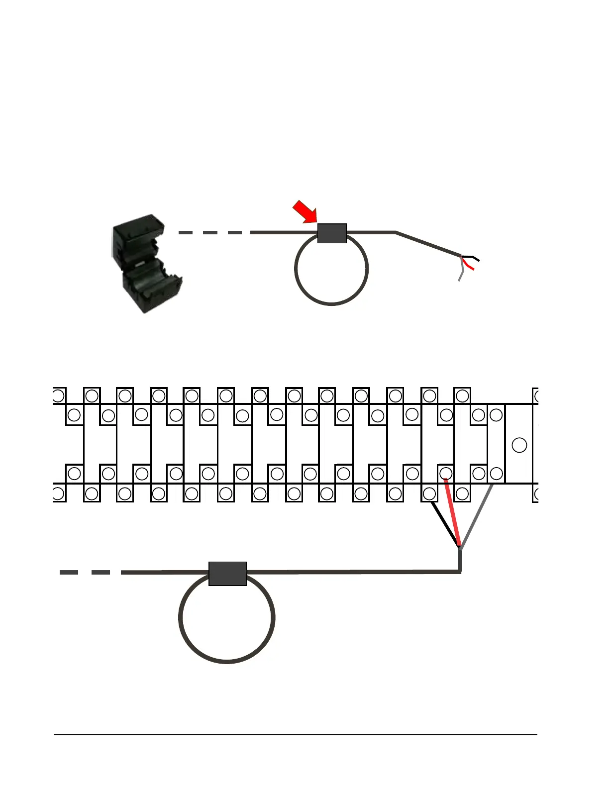
1. Using the field-provided shielded cable, make a small service loop after entering the controller and attach the provided
EMI filter at the intersection of the loop.
FIGURE 23
Communication Wiring: Termination at the Controller
2. Connect one wire to terminal #56 (negative), the other wire to terminal #57 (positive) and the drain wire to ground
terminal #60.
The steps outlined on the following pages show how to connect the communication wiring using the daisy chain
method shown in Figure 20. If using the alternate method (as shown in Figure 21), the connections to the controller
and each wall-mount unit will be the same but the filters need to be placed in the positions shown in Figure 22.
To Wall-Mount Unit 1
Control Board Terminal
Block
35
37
39 4341 45
47 51
49 53
55
59
57
6
8 10 12
14
16 18
20
22 24
26
28
30
32 34
36
38
40
42 44
46 48
50 52
54
56
58
1
2
3
4
63
61 65
67
71
69
62
64 66
68
70
72
60
–
+