38
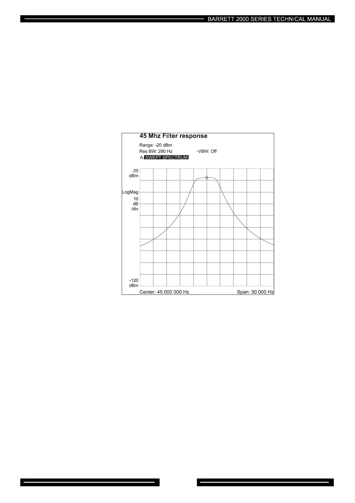
45MHz IF Filter
A spectrum analyser with tracking generator must be used to align this filter and it should be set with a
centre frequency of 45MHz and a span of 50kHz. Solder bridge SP1 and SP2 should be unsoldered, the
sweep signal should be injected at TP1 , the spectrum analyser input should be connected to TP2. L19 and
L20 should be adjusted to achieve the pass band shape as indicatedinFig1, with particular attention being
given to get the pass band as flat as possible. If a spectrum analyser is not available and either L19 or L20
or the crystal filter has to be replaced, rough alignment can be achieved by peaking the coils for maximum
output whilst injecting a weak signal. Note: - Whilst the transceiver will operate using this method the
filter shape could be incorrect and adjacent channel selectivity, blocking performance and transmit
purity may be compromised.
Figure1
Power amplifier (PA) PCB
There are three potentiometers on the PA PCB. These control the bias for the driver FETs (RV3) and
(RV4), and the PA transistors. (RV2). All PA potentiometers have been factory set and should only be
adjusted in the event of PA or driver transistor replacement. No other adjustments are provided.
Driver bias setup
If the driver FETs have been replaced, RV3 RV4 should be set fully anticlockwise. Power can then be
applied to the transceiver and PTT operated. Set the transceiver to about 7 MHz, and apply a two tone test
signal to the line input. With the front panel menu, set the line input level to -12dBm. This is to ensure that
the audio compressor is in compression to allow testing to full output power. Use 0dBm on the line input.
Apply PTT and using a spectrum analyser, adjust RV3 to give minimum intermodulation distortion. Back off
RV3 slightly. Adjust RV4 for minimum intermodulation distortion.
If no spectrum analyser is available, an oscilloscope can be used to judge best envelope shape whilst
adjusting RV3 and RV4. If unfamiliar with how the envelope should appear, a reasonable compromise can
be reached by removing link LK1 and placing an ammeter across the link terminals. With no input signal
applied, press PTT and adjust RV3 to give 50 mA of current. Now adjust RV4 until the meter reads 100mA.
Replace link LK1 and check that the PA delivers full power.