2.2.6.
WRITE
PROTECT
DETECTOR
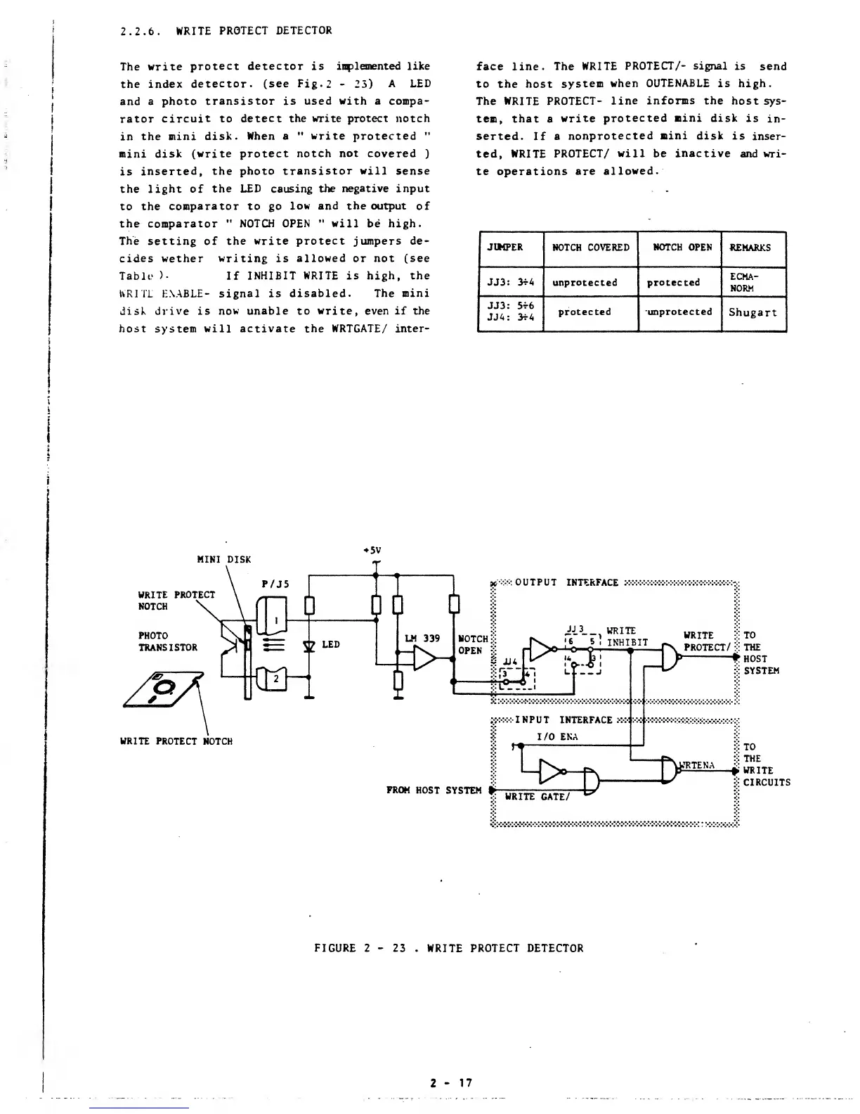
The
write
protect detector is implemented like
the index
detector, (see Fig.
2
-
25)
A LED
and
a photo
transistor is used
with
a compa-
rator
circuit to
detect the write protect notch
in
the mini
disk.
When a
"
write
protected
"
mini disk
(write protect notch
not
covered
)
is
inserted,
the
photo transistor will sense
the
light of
the LED
causing
the
negative
input
to the
comparator to go
low and the output
of
the
comparator
"
NOTCH OPEN
"
will be high.
The
setting of
the write protect jumpers de-
cides wether
writing
is
allowed or not (see
Table
>•
If
INHIBIT
WRITE
is high,
the
WRITE ENABLE- signal is disabled.
The mini
disk drive is
now unable to write, even if the
host system will activate the
WRTGATE/ inter-
face line.
The
WRITE
PROTECT/- signal
is
send
to
the host
system
when
OUTENABLE
is high.
The WRITE
PROTECT-
line
informs
the
host sys-
tem, that a
write
protected mini disk
is
in-
serted.
If
a
nonprotected mini disk
is
inser-
ted,
WRITE
PROTECT/ will be
inactive
and
wri-
te operations
are
allowed.
JUMPER
NOTCH COVERED NOTCH OPEN
REMARKS
JJ3:
3t4
unprotected protected
ECMA-
NORM
JJ3:
5t6
JJA: 3rA
protected
unprotected
Shugart
MINI
DISK
5V
WRITE PROTECT
NOTCH
in
r
:>v. OUTPUT
INTERFACE
:•:•:•:•:•:•:•:•:•:•:•:
Ji
3
__,
WRITE
ubttp
*
'6
5]
INHIBIT ^ «"IL_,*
LM
339
NOTCH:::
|s^
jT
"
J!
IHHIBIT
^
SSreCT/
g
Mg^
op,
j
#1
|>pn^^
T
jfe
ji-i
\
J
WRITE PROTECT
NOTCH
gx:-:
INPUT
INTERFACE x-4:4>>>^>W*W:
:
:x-x.x.:.:
:
:
S
I/O
ENA
r*
FROM
HOST
SYSTEM
L
D>-r
v
W.
ubitt riTP/
*-*
TO
THE
*HOST
S
SYSTEM
a>
WRTENA
*
*T0
::
THE
WRITE
S
CIRCUITS
*
WRITE
GATE/
FIGURE 2
-
23
.
WRITE
PROTECT DETECTOR
2-17