3.1.3.
CONNECTING
CABLES
3.1.4.2.
SIGNAL
CONNECTOR
The mini
disk
is connected
to the host
system
by
two
connecting
cables,
the DC- cable
and
the interface cable.
The DC- cable
requires
direct
connection to
each
drive,
regardless
of connecting
configuration.
The interface
cable
is connected
to the various
connecting
configurations
(see
3.1.6.) and should
not
exceed
10
feet
in length.
The signal cable
is connected
to the mini
disk
drive through
connector J1.
Connector
Jl
is
a
34 pin PCB
edge card connector
located at
the rear of
the
disk
drive.
The
pins
are
numbered
from 1
to
34 with
the even
pins on
the
component side. Pin
2 is located
closest
to tlje
stepper motor and is
labelled. A key-
slot is
provided
between
pins
4
and b
for
optional
connector keying. Recommended
mating
connectors
for Jl are listed in Table
5-2
.
3.1.4.
CONNECTORS
3.1.4.1.
DC-
CONNECTOR
DC
power
is
connected
to
the disk drive
through
connector
JS. The input
pin assignments and
voltage
requirements
and voltage
requirements
are listed
in table
3-1.
PIN
No.
DC
VOLTAGE TOLERANCE
CURRENT
MAX.
RIPPLE
(P
"
P
)
1 12 V
*
0,6
V
1.75A
100 mV
2 12V RET
- -
-
3
*
5V RET
-
-
-
4
5
V
*
0,25
V
0,7
A
50
mV
PLUS
1,4
A MOTOR
STARTING CURRENT
FOR
MAX. 100
msec.
Voltages
to be
measured on
testpoints on
drive PCB
TABLE
3-1
.DC
-
POWER REQUIREMENTS
The return
lines for
+
12V and
5V
(
pins 2
and
3)
should be
separate
lines and must
be
connected
together in the system. DC
power
input
connector
JS is mounted
on the
compo-
nent
side of the
PCB
beside the stepper mo-
tor (see
Fig. 3-9
)•
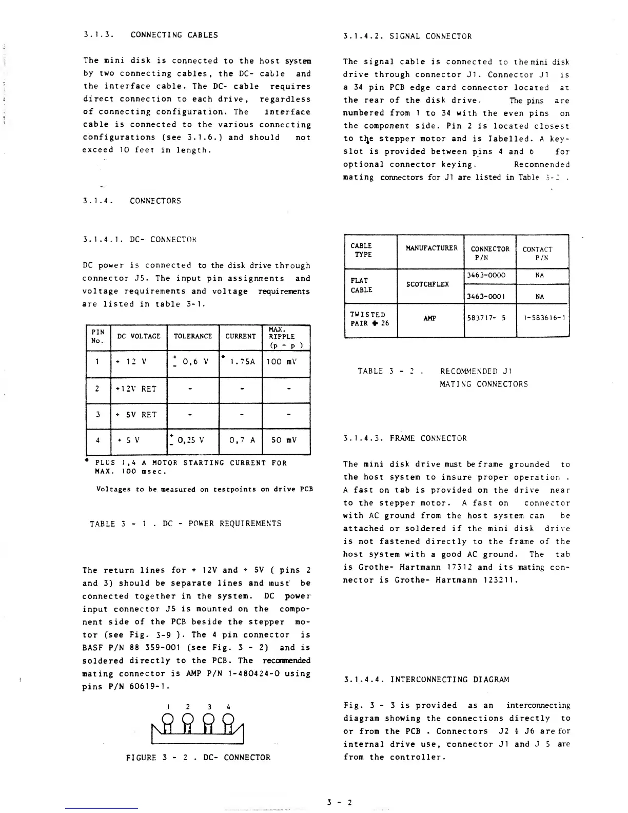
The
4 pin connector
is
BASF P/N
88
359-001
(see
Fig.
3-2)
and is
soldered
directly to
the
PCB. The reconmended
mating
connector is AMP P/N
1-480424-0
using
pins
P/N
60619-1.
k9
9
ft ft
A
CABLE
TYPE
MANUFACTURER
CONNECTOR
P/N
CONTACT
P/N
FLAT
CABLE
SCOTCHFLEX
34
6
3-0000
NA
3463-0001
NA
TWISTED
PAIR
*
26
AMP
583717-
5
1-583616-1
TABLE
3
-
2 .
RECOMMENDED Jl
MATING CONNECTORS
3.1.4.3.
FRAME CONNECTOR
The mini
disk drive must be frame
grounded to
the host system to insure proper
operation
.
A fast
on
tab
is
provided
on the drive
near
to
the stepper
motor.
A
fast
on
connector
with
AC ground from the host system can be
attached
or
soldered
if the mini
disk drive
is not fastened directly
to the
frame of the
host
system
with
a good AC ground. The
tab
is
Grothe-
Hartmann
17312
and its
mating
con-
nector is Grothe- Hartmann
123211.
FIGURE
3
-
2 .
DC- CONNECTOR
3.1.4.4.
INTERCONNECTING DIAGRAM
Fig. 3
-
3 is
provided
as an
interconnecting
diagram showing the connections directly
to
or from the PCB
. Connectors J2
*
J6 are
for
internal drive use, connector J1 and
J
5
are
from
the
controller.