AW00097209000 Configuring the Camera
Basler IP Fixed Box Cameras 57
3.9 Input / Output Parameters
The parameters in the Input/Output group are used to configure the camera’s digital I/O ports and
to configure the camera’s RS-485 serial port.
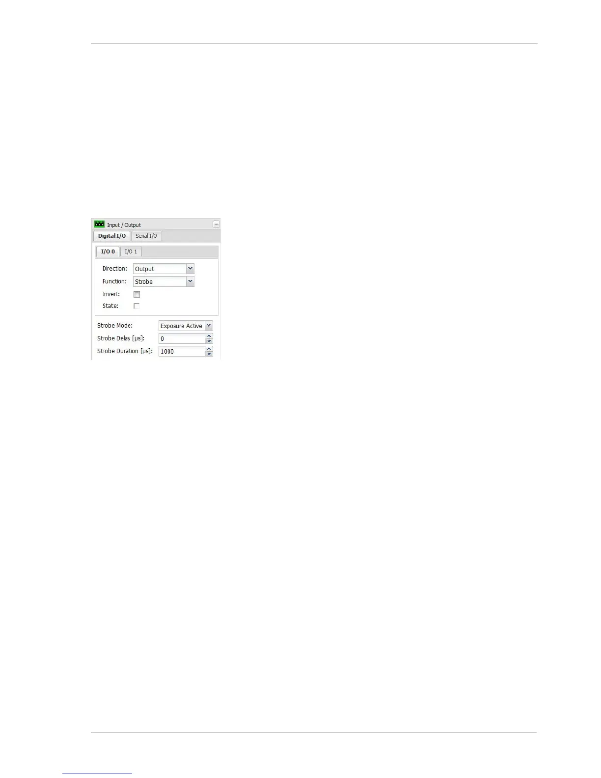
3.9.1 Digital I/O Tab
I/O Sub-Tabs
Direction - Sets whether the I/O port will act as an input or as an output.
Function - Sets the function for the I/O port. The list of available functions will be different
depending on whether the Direction parameter is set to input or output.
If the Direction parameter is set to input, the list of available functions will be:
Monitor = The state of the input port can be monitored only (using the State check box
described below). The camera will not react to any changes in the state of the port.
IR Switch = The input port will be used to control the position of the camera’s IR-cut filter. When
the port becomes active, the filter will move to the night position (filter is not in front of the
sensor). When the port becomes inactive, the filter will move to the day position (filter is in front
of the sensor).
For this function to operate correctly, the IR Filter Mode parameter on the Day/Night tab (see
Section 3.3.3 on page 17) must be set to "Input Controlled".
Alarm Trigger = The input port can be used to trigger an alarm condition on the camera. When
the port becomes active, an alarm condition will be declared.
For this function to operate correctly, the Source Enable box must be checked on the Digital In
tab in the Alarm Sources section of the Alarm Handling parameters (see page 42).
Real-time Trigger = The input port can be used to trigger the start of an image exposure. When
the port becomes active, an image exposure will begin 7 milliseconds later.
If the Source Enable box on the Digital In tab in the Alarm Sources section of the Alarm Handling
parameters is checked (see page 42), an alarm condition will also be declared when the port
becomes active.
For more details about the real-time trigger feature, see Section 7 on page 97.
The Digital I/O tab includes three sub-tabs. Each sub-tab is used to
configure one of the camera’s I/O ports. The three I/O ports are
designated as I/O 0, I/O 1, and I/O 2.
Each I/O port can be set to act as either an input or an output. The
settings on each tab let you specify whether the I/O port associated
with the tab will act as an input or an output and let you set the
function of the port.
The operation of each sub-tab is identical, and the description below
applies to all of the sub-tabs.
(For information about making electrical connections to the I/O
ports, see Section 5 on page 83.)

 Loading...


