9440300990 15-5
DECS-250 Power System Stabilizer
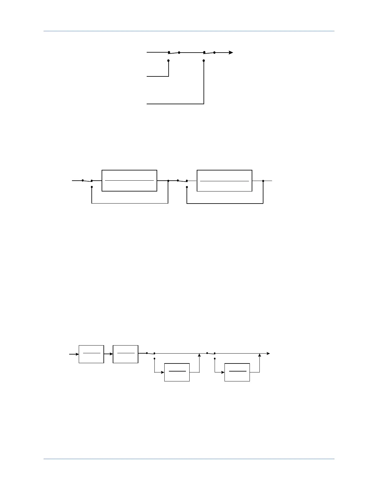
Figure 15-5. Stabilizing Signal Selection
Torsional Filters
Two torsional filters, shown in Figure 15-6, are available after the stabilizing signal and before the phase
compensation blocks. The torsional filters provide the desired gain reduction at a specified frequency.
The filters compensate the torsional frequency components present in the input signal.
Figure 15-6. Torsional Filters
Software switch SSW 4 enables and disables torsional filter 1 and SSW 5 enables and disables torsional
filter 2.
Torsional filters 1 and 2 are controlled by a zeta numerator (Zeta Num), zeta denominator (Zeta Den),
and a frequency response parameter (Wn).
Phase Compensation
The derived speed signal is modified before it is applied to the voltage regulator input. Filtering of the
signal provides phase lead at the electromechanical frequencies of interest (0.1 to 5 Hz). The phase lead
requirement is site-specific and is required to compensate for phase lag introduced by the closed-loop
voltage regulator.
Four phase compensation stages are available. Each phase compensation stage has a phase lead time
constant (T1, T3, T5, T7) and a phase lag time constant (T2, T4, T6, T8). Normally, the first two lead-lag
stages are adequate to match the phase compensation requirements of a unit. If needed, the third and
fourth stages may be added through the settings of software switches SSW 6 and SSW 7. Figure 15-7
illustrates the phase compensation stages and associates software switches.
Figure 15-7. Phase Compensation
Washout Filter and Logic Limiter
The output of the phase compensation stages is connected, through a stabilizer gain stage, to the
washout filter and logic limiter.
Software switch SSW 9 enables and bypasses the washout filter and logic limiter. The washout filter has
two time constants: normal and limit (less than normal).
P0026
-19
12-09-04
Derived
Speed
Deviation
SSW 2
Washed
Out Speed
SSW 3
Stabilizing
Signal
Washed
Out Power
2
2
2
2
2
2
nn
d
n
nn
wsw
zs
w
sw
zs
++
+
+
2
2
2
2
2
2
nnd
n
nn
w
swzs
w
sw
zs
+
+
+
+
Phase
Compensation
P0026-20
12-09-04
Disable
SSW 5
SSW 4
Enable
Disable
Enable
1 + s T
1
1 + s T
2
1 + s T
3
1 + s T
4
PSS Output Before
Gain and Limits
Stabilizing
Signal
Include
Exclude
SSW 6
1 + s T
5
1 + s T
6
SSW 7
1 + s T
7
1 + s T
8
P0026-21
12-09-04
Include
Exclude