9440300990 18-5
DECS-250 Terminals and Connectors
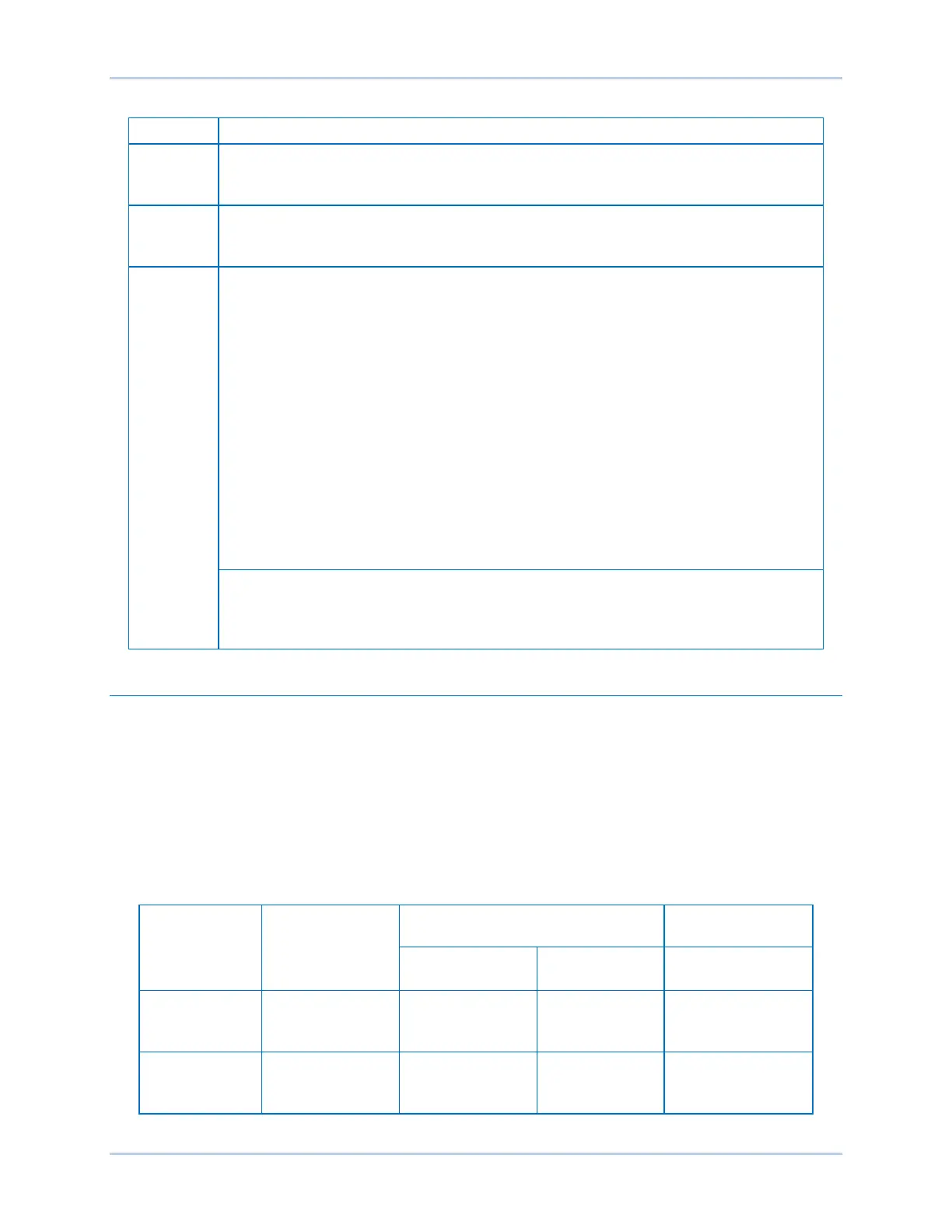
Table 18-2. Right Side Terminal and Connector Descriptions
A second DECS-250 connects through a standard serial cable to this DB-9 connector
for the purpose of setpoint tracking. Setpoint tracking between a DECS-250 and
This DB-9 connector is provided for PROFIBUS communication (style xxxxxxP) and
the future implementation of other communication protocols. Contact Basler Electric
for protocol availability.
Three terminal sets within this block include two CAN communication ports and an
IRIG input. The IRIG terminals connect to an IRIG source for synchronization of
DECS-250 timekeeping with the IRIG source. Both CAN ports are SAE J1939
compliant. CAN 1 is used to connect add-on modules such as the Basler Electric
CEM-2020 and AEM-2020. CAN 2 is used to communicate with a genset engine
controller.
The terminal numbers (shown below) are located on the mating side of the
connector.
• 96 - CAN 1 High
• 97 - CAN 1 Low
• 98 - CAN 1 Shield
• 99 - CAN 2 High
• 100 - CAN 2 Low
• 101 - CAN 2 Shield
• 102 - IRIG +
This optional Ethernet communication port uses the Modbus TCP protocol to provide
remote metering, annunciation, and control. A copper (100Base-T) port (style
xxxxx1x) uses a standard RJ45 jack while a fiber optic (100Base-FX) port (style
xxxxx2x) uses two fiber optic connectors (not shown).
Terminal Types
Spring terminals are supplied on DECS-250 controllers with a style number of xxxSxxx. These removable
connectors secure each wire with a spring-loaded contact.
Compression terminals are supplied for the operating power terminals (locator A), field power output
terminals (locator B), and current sensing terminals (locator C) when a style number of xxxCxxx is
specified. The remaining connectors use spring terminals.
Table 18-3 lists the acceptable wire sizes, strip lengths, and screw torques (compression terminals only)
for each terminal block. The locator letters used in Table 18-3 correspond to the locator letters shown in
Figure 18-1 and Figure 18-2.
Table 18-3. Connector Wiring Specifications
Terminal
Maximum
10 mm
2
(solid)
2
(0.75 N•m)
I, J
2.5 mm
2
(solid