9440300990 21-9
DECS-250 BESTlogic™Plus
Name Description Symbol
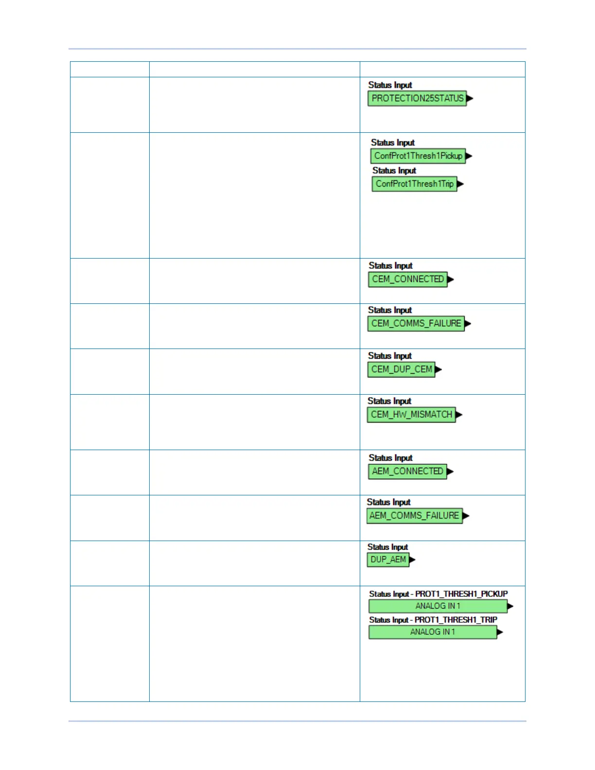
Protection Several protection status alarms are available. The
25 Sync-Check Status Alarm input is shown to the
right. These elements are true when the pickup
threshold is exceeded for the duration of the time
delay.
Configurable
Protection 1-8
There are four thresholds for each of the eight
Configurable Protection blocks. Each threshold can
be set to Over or Under mode and the threshold
limit and activation delay can each be set. See the
Protection chapter in this manual for more details.
Each threshold has a separate logic block for the
pickup and the trip. Configurable Protection #1 with
its Threshold #1 Pickup and Trip blocks is shown to
the right. The pickup block is true when the
threshold is exceeded. The trip block is true when
the corresponding pickup block threshold is
exceeded for the duration of the time delay.
Contact
Expansion
Module, CEM
Connected
Contact Expansion Module Connected. True when
an optional CEM-2020 is connected to the DECS-
250.
Contact
Expansion
Module, Comms
Failure
True when there is no communication from the
CEM.
Contact
Expansion
Module,
Duplicate CEM
True when more than one CEM is detected. Only
one CEM is supported at a time.
Contact
Expansion
Module,
Hardware
Mismatch
True when selected CEM type differs from detected
CEM type. Go to Settings Explorer,
Communications, CAN Bus, Remote Module Setup
to select the CEM type (18 or 24 contacts).
Analog
Expansion
Module,
Connected
Analog Expansion Module Connected. True when
an optional AEM-2020 is connected to the DECS-
250.
Analog
Expansion
Module, Comms
Failure
True when there is no communication from the
AEM.
Analog
Expansion
Module,
Duplicate AEM
True when more than one AEM is detected. Only
one AEM is supported at a time.
Analog
Expansion
Module,
Remote Analog
Inputs 1-8
There are four thresholds for each of the eight
Remote Analog Input blocks. Each threshold has a
separate logic block for the pickup and the trip.
Remote Analog Input #1 with its Threshold #1
Pickup and Trip blocks is shown to the right. For
more details on configuring the Remote Analog
Inputs, see the Analog Expansion Module chapter
in this manual. The pickup block is true when the
threshold is exceeded. The trip block is true when
the corresponding pickup block threshold is
exceeded for the duration of the time delay.