9440300990 5-3
DECS-250 Voltage and Current Sensing
If a machine is taken offline, then the secondary winding of that
machine’s cross-current compensation CT must be shorted.
Otherwise, the cross-current compensation scheme will not function.
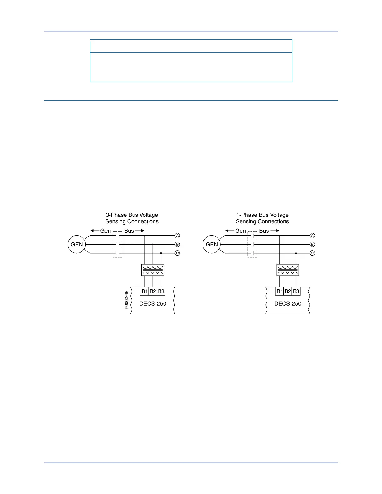
Bus Voltage
Bus voltage monitoring enables bus failure detection, generator and bus voltage matching, and
synchronization of the generator with the utility/bus. These features are discussed in the Synchronizer
chapter of this manual. Three-phase bus sensing voltage is applied to DECS-250 terminals B1, B2, and
B3. This sensing voltage is typically applied through a user-supplied voltage transformer, but may be
applied directly. These terminals accept three-phase, three-wire connections at terminals B1 (A), B2 (B),
and B3 (C) or single-phase connections at B3 (C) and B1 (A).
The bus voltage sensing input accepts a maximum voltage of 600 Vac and has a burden of less than 1
VA.
The transformer primary and secondary winding voltages are entered in settings that the DECS-250 uses
to interpret the applied sensing voltage. Information about configuring the DECS-250 for the bus sensing
voltage is provided in the Configuration chapter of this manual.
Typical bus voltage sensing connections are illustrated in Figure 5-4.
Figure 5-4. Typical Bus Voltage Sensing Connections