29-2 9440300990
PROFIBUS Communication DECS-250
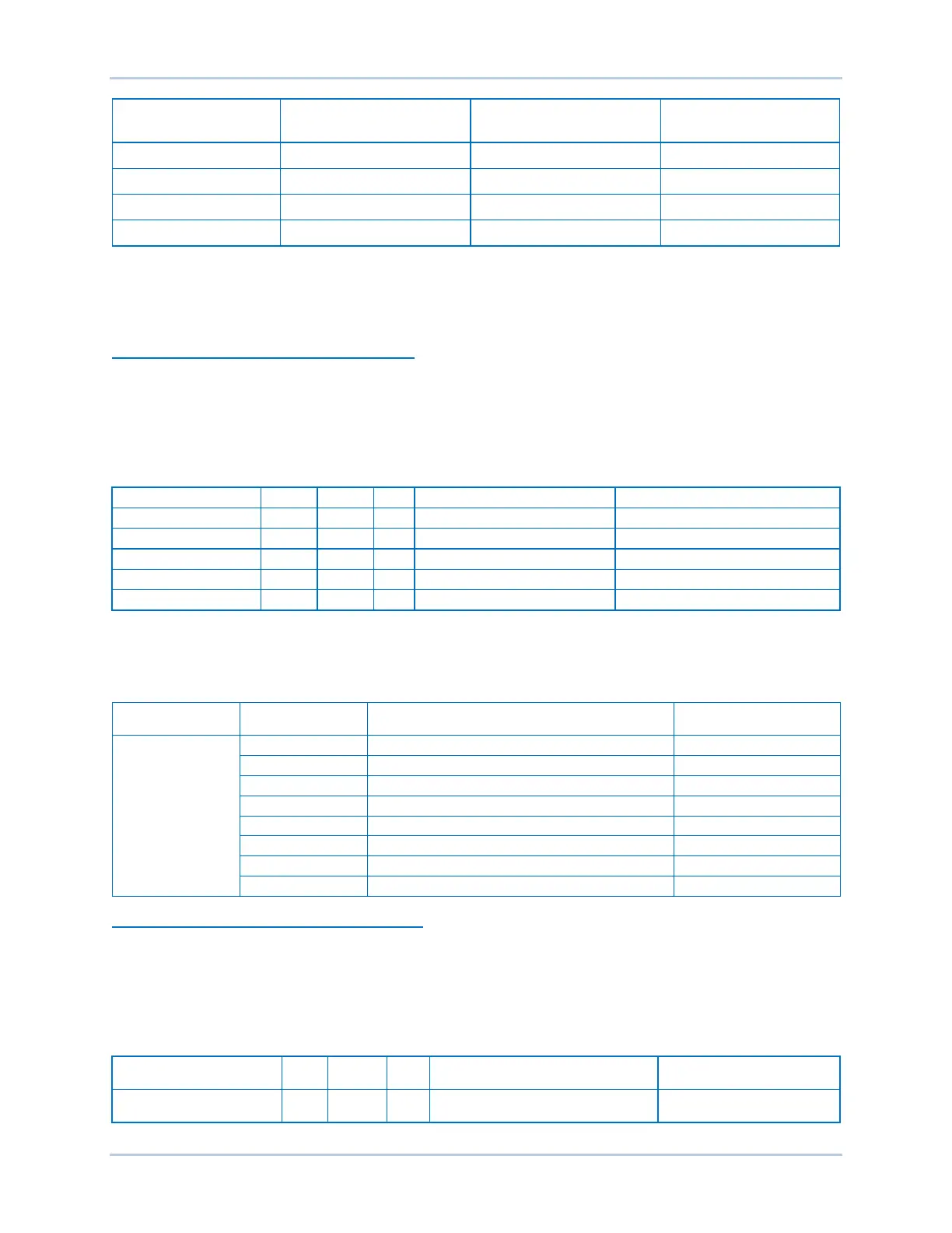
Instance Number
Number of Parameters
in the Instance
Number of Parameters
Divided by Eight
Total Data Size
Within these instances, the data is packed in the order listed in Table 29-6. The first item is the lowest bit
of the first byte. If there are unused bits, they are filled with a value of zero. Parameters of UINT8 type are
not affected by the DECS-250 Network Byte Order setting. The examples, below, show the bit packing
order for instances 8 (Controller Status Cyclic) and 11 (Local Contact Outputs Cyclic).
Example 1: Bit Packing Order for Instance 8
The total data size of Instance 8 is one byte. Table 29-2 shows the parameters of instance 8 as they
appear in Table 29-6. The first parameter in instance 8, with key name DECSCONTROL IN AVR MODE,
is represented by the lowest bit in the byte (bit 0). Bit 1 represents the next parameter with key name
DECSCONTROL IN FCR MODE and so on. The three highest bits in this instance are unused and thus
always return a value of zero.
Table 29-2. Instance 8 Parameters
Not in AVR mode=0, In AVR mode=1
Not in FCR mode=0, In FCR mode=1
Not in FVR mode=0, In FVR mode=1
Not in PF mode=0, In PF mode=1
Not in var mode=0, In var mode=1
Table 29-3 shows the bit number of each parameter in instance 8 and an example packet returned from a
DECS-250. Reading a value of 0x02 (0000 0010) for instance 8 indicates that the device is operating in
FCR mode.
Table 29-3. Instance 8 Bit Order
Instance Number Bit Number Key Name
Packet Returned from
DECS-250
Example 2: Bit Packing Order for Instance 11
The total size of Instance 11 is two bytes. Table 29-4 shows the parameters of instance 11 as they
appear in Table 29-6. The first parameter in instance 11, with key name CONTACTOUTPUTS
WATCHDOGOUTPUT, is represented by the lowest bit in the first byte (bit 0). The ninth parameter, with
key name CONTACTOUTPUTS OUTPUT8, is represented by the lowest bit in the second byte (bit 0).
The four highest bits in the second byte are unused and thus always return a value of zero.
Table 29-4. Instance 11 Parameters
Instance Name
Type RW Key Name Range
Local Contact Outputs Cyclic 11 UINT8 R
CONTACTOUTPUTS
WATCHDOGOUTPUT