9440300990 29-3
DECS-250 PROFIBUS Communication
Instance Name
Type RW Key Name Range
Local Contact Outputs Cyclic 11 UINT8 R CONTACTOUTPUTS OUTPUT1
Local Contact Outputs Cyclic 11 UINT8 R CONTACTOUTPUTS OUTPUT2
Local Contact Outputs Cyclic 11 UINT8 R CONTACTOUTPUTS OUTPUT3
Local Contact Outputs Cyclic 11 UINT8 R CONTACTOUTPUTS OUTPUT4
Local Contact Outputs Cyclic 11 UINT8 R CONTACTOUTPUTS OUTPUT5
Local Contact Outputs Cyclic 11 UINT8 R CONTACTOUTPUTS OUTPUT6
Local Contact Outputs Cyclic 11 UINT8 R CONTACTOUTPUTS OUTPUT7
Local Contact Outputs Cyclic 11 UINT8 R CONTACTOUTPUTS OUTPUT8
Local Contact Outputs Cyclic 11 UINT8 R CONTACTOUTPUTS OUTPUT9
Local Contact Outputs Cyclic 11 UINT8 R CONTACTOUTPUTS OUTPUT10
Local Contact Outputs Cyclic 11 UINT8 R CONTACTOUTPUTS OUTPUT11
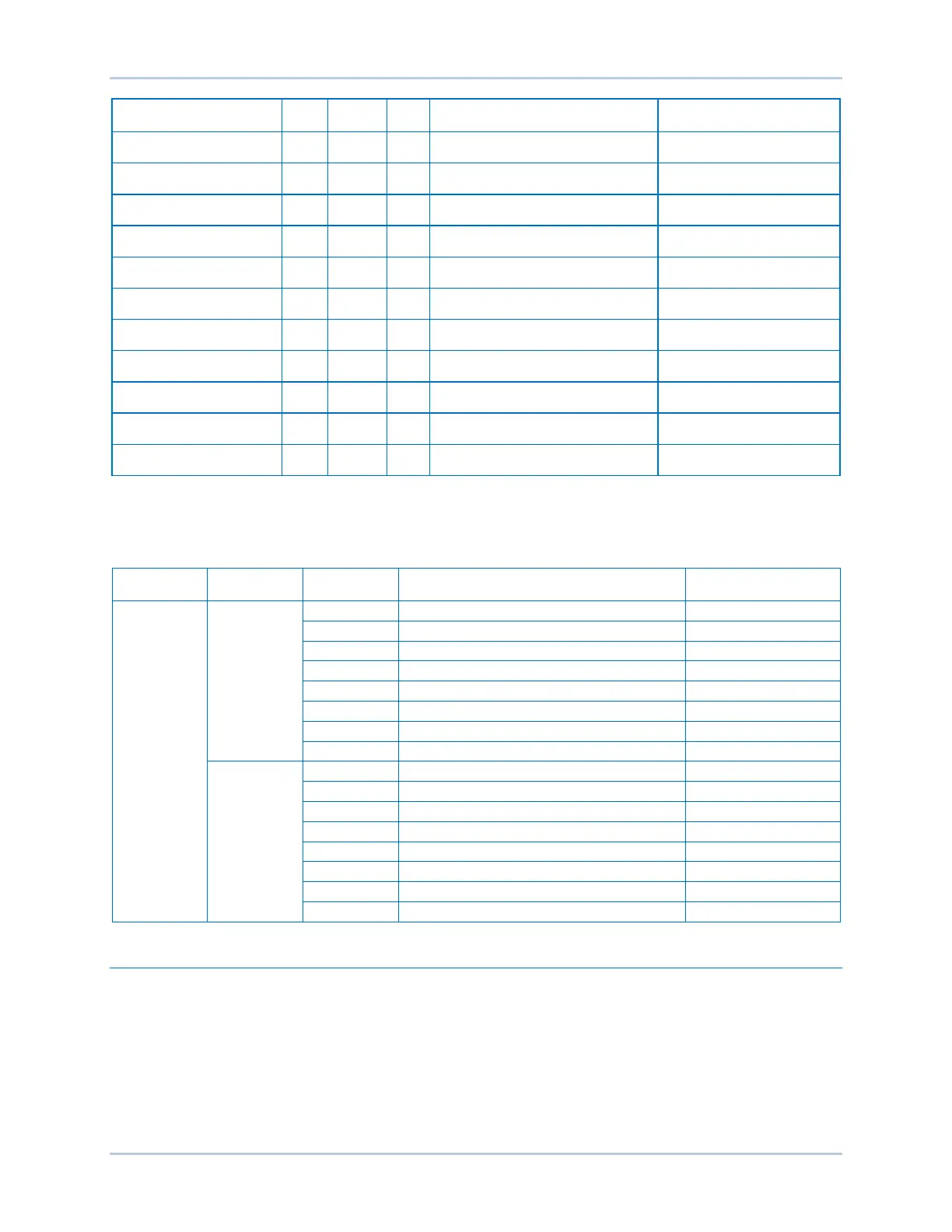
Table 29-5 shows the bit number of each parameter in instance 11 and an example packet returned from
a DECS-250. Reading a value of 0xA4 06 (1010 0100 0000 0110) for instance 11 indicates that contact
outputs 2, 5, 7, 9, and 10 are closed. The first byte is 1010 0100 and the second is 0000 0110.
Table 29-5. Instance 11 Bit Order
Byte Number Bit Number Key Name
Packet Returned from
DECS-250
Setup
The following steps are provided to assist in setting up the DECS-250 as a slave on a PROFIBUS
network. Please refer to the documentation included with your PLC configuration software for installation
and operation instructions.
1. Download the DECS-250 GSD file from the Basler website: www.basler.com
2. Using PLC configuration software, import the GSD file. This allows the DECS-250 to be included in
the bus configuration as a slave.
3. Assign a unique PROFIBUS address to the DECS-250. This allows the master to exchange data with
the DECS-250.