EasyManua.ls Logo

Basler DECS-250 - Page 280

Basler DECS-250
374 pages
Print Icon
To Next Page IconTo Next Page
To Previous Page IconTo Previous Page
Loading...
29-4 9440300990
PROFIBUS Communication DECS-250
4. Select modules from the GSD file to be part of the data exchange. Selecting the cyclic parameters is
recommended. The cyclic parameters are comprised of the first 12 instances in the PROFIBUS
parameters table (Table 29-6). Instances 1 through 5 consist of 25 float types. Instances 6 through 12
consist of 9 UINT8 types.
5. Set each selected module to an address in the master's memory bank.
6. Compile and download the configuration to the master before going online.
When the PROFIBUS network is initialized, the master connects to each slave checking for address
mismatches and sending configuration data. The configuration data is sent so that the master and slave
agree on the data exchange to occur. Then, the master begins polling each slave in a cyclic order.
Note
It is not possible to write a portion of an instance by specifying a length
smaller than the size of the instance. To modify a single parameter,
read the entire instance, update the desired parameter, and write the
entire instance back to the device.
PROFIBUS Parameters
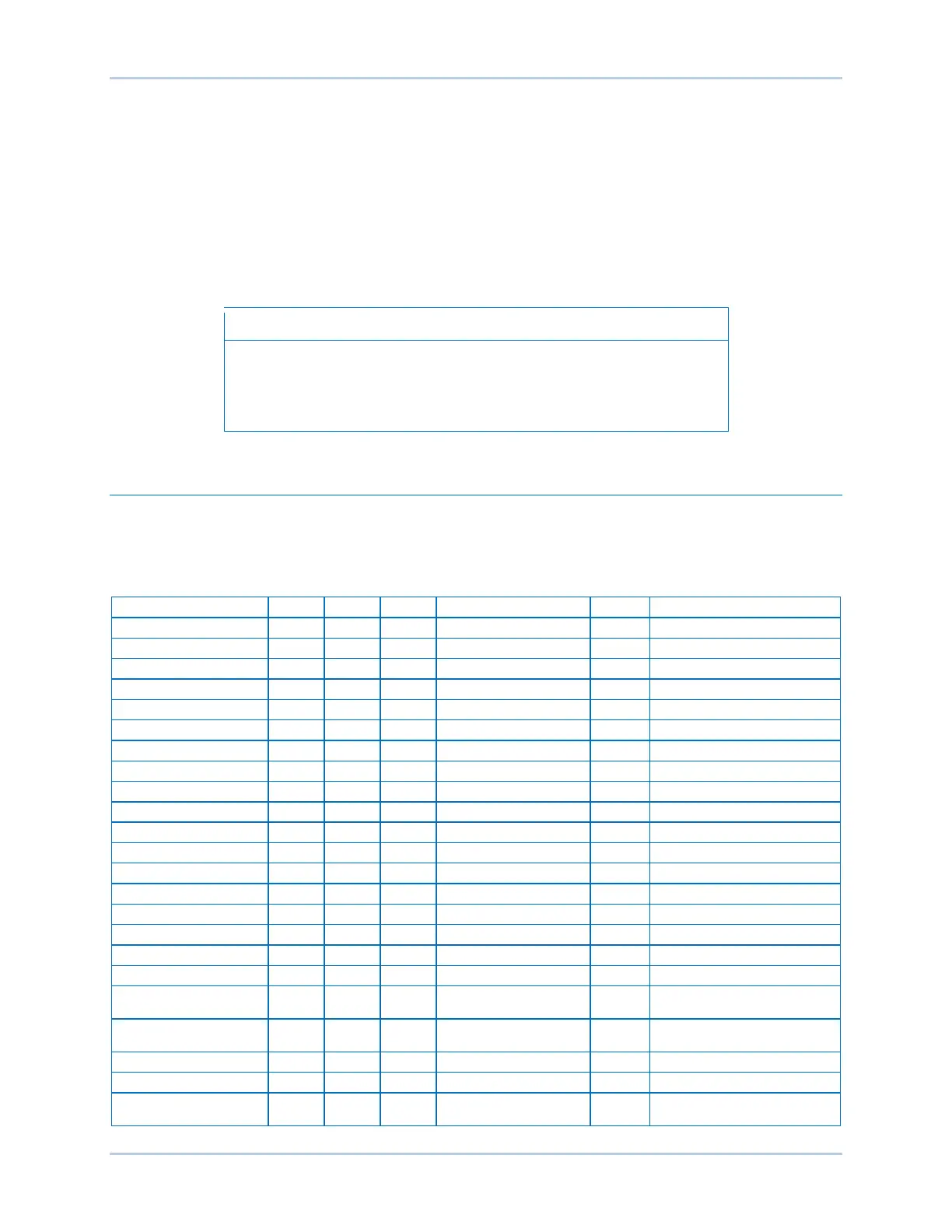
PROFIBUS parameters are listed in Table 29-6. Instances with names ending in cyclicare automatically
transmitted at a periodic rate. All other instances are acyclic and transmitted only when requested by the
PLC.
Table 29-6. PROFIBUS Parameters
Instance Name
Inst. #
Type
RW
Key Name
Unit
Range
Gen Metering Cyclic
1
Float
R
VAB GG
V
0 - 2000000000
Gen Metering Cyclic
1
Float
R
VBC GG
V
0 - 2000000000
Gen Metering Cyclic
1
Float
R
VCA GG
V
0 - 2000000000
Gen Metering Cyclic
1
Float
R
IA GG
Amp
0 - 2000000000
Gen Metering Cyclic
1
Float
R
IB GG
Amp
0 - 2000000000
Gen Metering Cyclic
1
Float
R
IC GG
Amp
0 - 2000000000
Gen Metering Cyclic
1
Float
R
Freq GG
Hz
10 - 180
Gen Metering Cyclic
1
Float
R
Total Watts AVG GG
Watt
-3.00E+14 - 3.00E+14
Gen Metering Cyclic
1
Float
R
Total VARS AVG GG
Var
-3.00E+14 - 3.00E+14
Gen Metering Cyclic
1
Float
R
Total S GG
VA
-3.00E+14 - 3.00E+14
Gen Metering Cyclic
1
Float
R
Total PF GG
PF
-1 - 1
Bus Metering Cyclic
2
Float
R
VAB GG
V
0 - 2000000000
Bus Metering Cyclic
2
Float
R
VBC GG
V
0 - 2000000000
Bus Metering Cyclic
2
Float
R
VCA GG
V
0 - 2000000000
Bus Metering Cyclic
2
Float
R
Freq GG
Hz
10 - 180
Field Metering Cyclic
3
Float
R
VX GG
V
-1000 - 1000
Field Metering Cyclic
3
Float
R
IX GG
Amp
0 - 2000000000
Setpoint Metering Cyclic
4
Float
R
Gen Voltage Setpoint GG
V
84 - 144
Setpoint Metering Cyclic
4
Float
R
Excitation Current Setpoint
GG
Amp
0 - 12
Setpoint Metering Cyclic
4
Float
R
Excitation Voltage Setpoint
GG
V
0 - 75
Setpoint Metering Cyclic
4
Float
R
Gen Var Setpoint GG
kvar
0 41.57
Setpoint Metering Cyclic
4
Float
R
Gen Pf Setpoint GG
PF
0.5 – -0.5
Synchronizer Metering
Cyclic
5
Float
R
Slip Angle GG
Deg
-359.9 - 359.9

Related product manuals