9440300990 6-3
DECS-250 Synchronizer
Voltage Matching
BESTCOMSPlus Navigation Path: Settings Explorer, Synchronizer/Voltage Matching, Voltage Matching
HMI Navigation Path: Settings, Sync/Voltage Matching, Voltage Matching
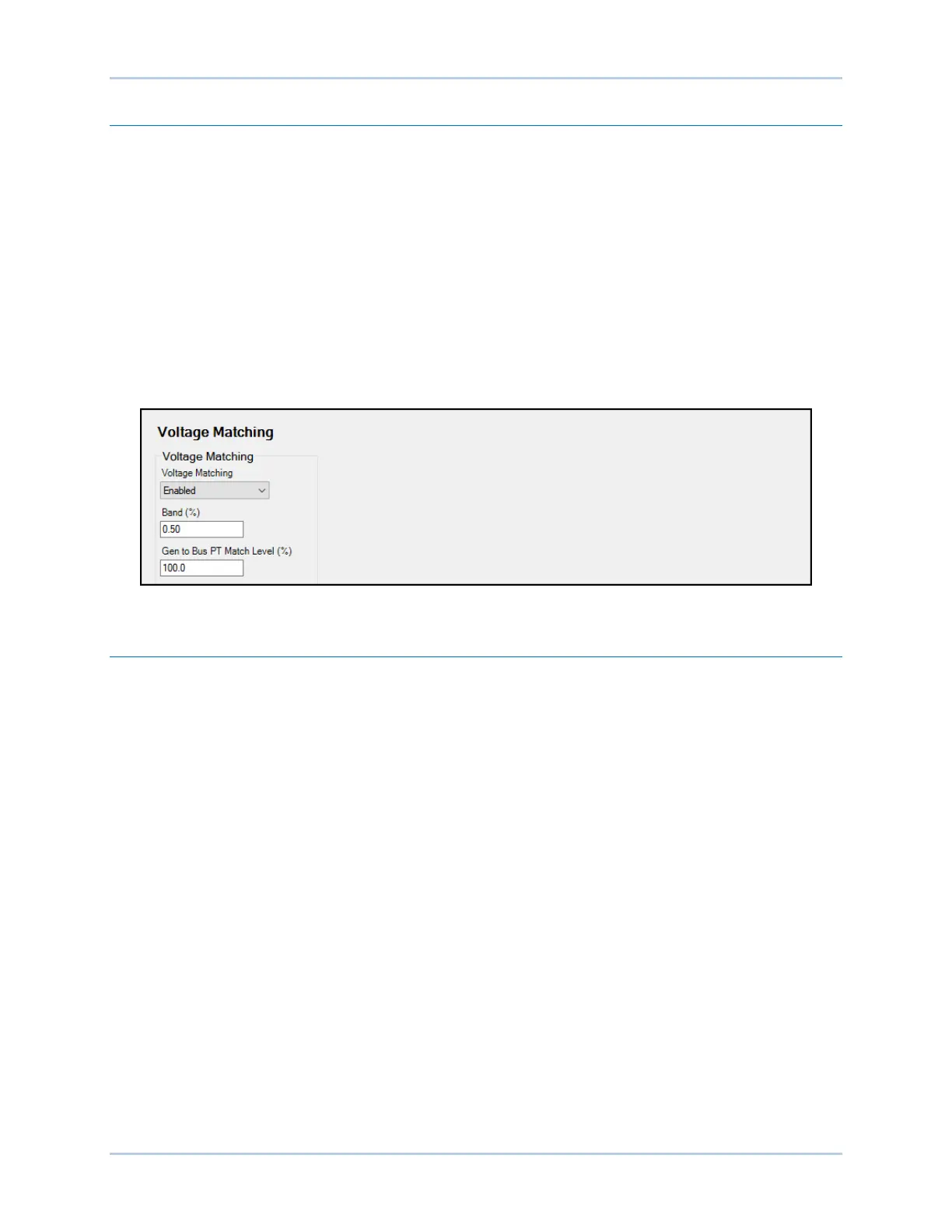
When enabled, voltage matching is active in AVR control mode and automatically adjusts the AVR mode
setpoint to match the sensed bus voltage. Voltage matching is based on two parameters: band and
matching level.
The voltage matching band defines the window in which the generator voltage must be for voltage
matching to occur.
A generator to bus PT matching level setting is provided to compensate for step-up or step-down
transformers in the system. The DECS-250 adjusts the sensed generator voltage by this percentage. This
setting also appears on the Synchronizer screen, above. When the value is changed, it is reflected in both
places. To calculate the appropriate Gen to Bus PT Match Level value, refer to Equation 6-2.
Voltage matching settings are illustrated in Figure 6-2.
Figure 6-2. Voltage Matching Settings
Breaker Hardware Configuration
BESTCOMSPlus Navigation Path: Settings Explorer, Synchronizer/Voltage Matching, Breaker
Hardware
HMI Navigation Path: Settings, Sync/Voltage Matching, Breaker Hardware
The DECS-250 can control and monitor a generator breaker. Breaker hardware settings are illustrated in
Figure 6-3.
Breaker Failure
When a close command is issued to the breaker, the DECS-250 monitors the breaker status and
annunciates a breaker failure if the breaker does not close within the time defined by the breaker close
wait delay. Typically, the wait delay is set to be longer than the actual breaker closing time.
Generator Breaker
The DECS-250 must be configured with the generator breaker characteristics before the breaker can be
controlled by the DECS-250. Breakers controlled by pulse or continuous control inputs are supported.
During anticipatory-mode synchronization, if the generator breaker is serving to tie the generator to the
bus, the DECS-250 uses the breaker closing time to calculate the optimum time to close the breaker. For
a pulse-controlled generator breaker, the breaker open and close pulse times are used by the DECS-250
when issuing open and close commands to the breaker. When setting the pulse times, the open and
close times should be set at or longer than the breaker closing time setting.
If desired, breaker closure is possible during a dead bus condition and/or dead generator condition.