9440300990 32-13
DECS-250 Analog Expansion Module
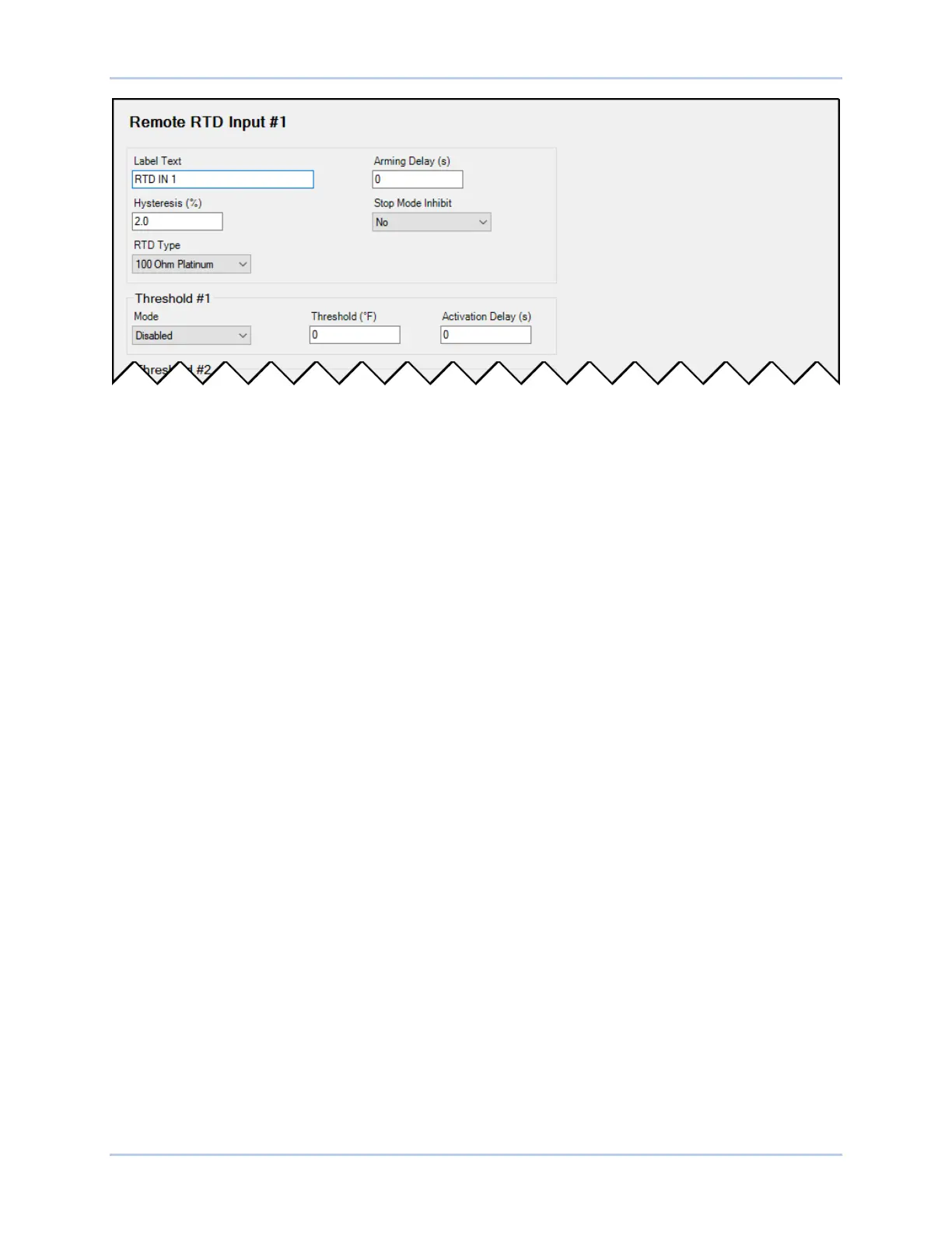
Figure 32-13. Remote RTD Input Settings
Thermocouple Inputs
BESTCOMSPlus Navigation Path: Settings, Programmable Inputs, Remote Thermocouple Inputs
HMI Navigation Path: Settings, Programmable Inputs, Remote Thermocouple Inputs
The AEM-2020 provides two thermocouple inputs. The thermocouple inputs are always monitored and
their status is displayed on the appropriate metering screens. To make identifying the thermocouple
inputs easier, a user-assigned name can be given to each input.
Select the amount of hysteresis needed to prevent rapid switching of the alarm. A user-adjustable arming
delay allows configuration of the thermocouple input threshold monitoring in one of two ways. (1) When
the arming delay is set to zero, threshold monitoring is performed all the time, whether or not excitation is
enabled. (2) When the arming delay is set to a non-zero value, threshold monitoring begins when the
arming delay time has expired after system startup is complete. An out-of-range alarm, configured on the
Alarm Configuration, Alarms screen in BESTCOMSPlus, alerts the user of an open or damaged
thermocouple input wire. When enabled, Stop Mode Inhibit turns off thermocouple input protection when
excitation is stopped.
Each thermocouple input can be independently configured for over or under mode to annunciate an alarm
when the thermocouple input signal falls beyond the threshold. Alarms are configured on the Alarm
Configuration, Alarms screen in BESTCOMSPlus. A user-adjustable activation delay setting delays alarm
annunciation after the threshold has been exceeded.
The remote thermocouple inputs are incorporated into a BESTlogicPlus programmable logic scheme by
selecting them from the I/O group in BESTlogicPlus. For more details, refer to the BESTlogicPlus chapter.
BESTCOMSPlus® settings for remote thermocouple inputs are illustrated in Figure 32-14. Remote
Thermocouple Input #1 is shown.