9440300990 7-3
DECS-250 Regulation
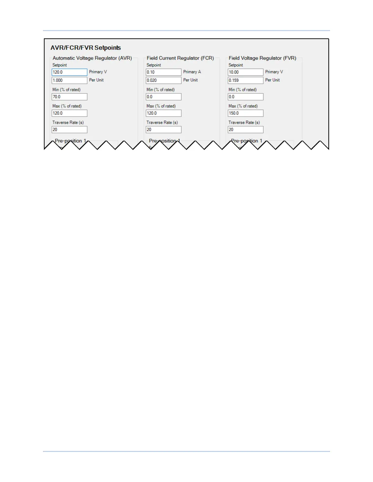
Figure 7-1. AVR, FCR, and FVR Regulation Settings
Var
When operating in var mode, the DECS-250 regulates the reactive power (var) output of the generator
based on the var setpoint. The setting range of the var setpoint depends on the generator ratings and
other associated settings. Var setpoint adjustment is made through:
• Application of contacts at DECS-250 contact inputs configured for raising and lowering the active
setpoint
• Application of an analog control signal at the DECS-250 Auxiliary Control input
• The BESTCOMSPlus Control Panel screen (available in the BESTCOMSPlus Metering Explorer)
• A raise or lower command transmitted through the DECS-250 Modbus port
The range of adjustment is defined by Minimum and Maximum settings that are expressed as a
percentage of the generator rated kVA output. The length of time required to adjust the Var setpoint from
one limit to the other is controlled by a Traverse Rate setting. A Fine Voltage Adjustment Band setting
defines the upper and lower boundaries of voltage correction when operating in var or power factor
regulation modes.
Settings that are related to machine ratings can be set in either actual units of voltage or in per unit
values. When a native unit is edited, BESTCOMSPlus automatically recalculates the per unit value based
on the native unit setting and the rated data parameter (on the System Parameters, Rated Data screen)
associated with it. When a per unit value is edited, BESTCOMSPlus automatically recalculates the native
value based on the per unit setting and the rated data parameter associated with it.
Once all per unit values are assigned, if the rated data parameters are changed, BESTCOMSPlus
automatically recalculates all native unit settings based on the modified rated data parameters.
The Reactive Power Control setpoint has a native unit of Primary kvar and the rated data associated with
it is Machine Rated Data, Rating (kVA) (on the System Parameters, Rated Data screen).
Var mode settings are illustrated in Figure 7-2.
Power Factor
When operating in Power Factor (PF) mode, the DECS-250 controls the var output of the generator to
maintain the Power Factor setpoint as the kW load on the generator varies. The setting range of the PF
setpoint is determined by the PF – Leading and PF – Lagging settings. The length of time required to
adjust the PF setpoint from one limit to the other is controlled by a Traverse Rate setting. A Fine Voltage
Adjustment Band setting defines the upper and lower boundaries of voltage correction when the DECS-
250 is operating in Var or Power Factor regulation modes. PF Active Power Level establishes the level of
generator output power (kW) where the DECS-250 switches to/from Droop Compensation/Power Factor
mode. If the level of power decreases below the setting, the DECS-250 switches from Power Factor mode
to Droop Compensation mode. Conversely, as the level of power increases above the setting, the DECS-