7-4 9440300990
Regulation DECS-250
250 switches from Droop Compensation mode to Power Factor mode. A setting of 0 to 30% may be
entered in 0.1% increments.
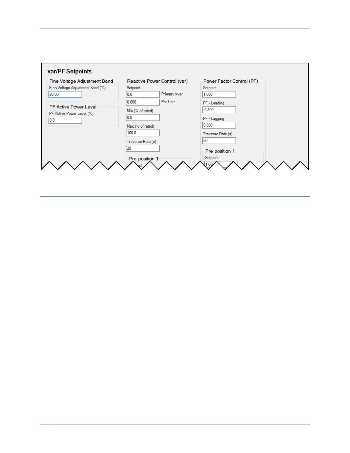
Power Factor mode settings are illustrated in Figure 7-2.
Figure 7-2. Var and Power Factor Regulation Settings
Pre-Position Setpoints
Each regulation mode has three pre-position setpoints which allow the DECS-250 to be configured for
multiple system and application needs. Each pre-position setpoint can be assigned to a programmable
contact input. When the appropriate contact input is closed, the setpoint is driven to the corresponding
pre-position value.
Each pre-position function has three settings: Setpoint, Traverse Rate, and Mode. The setting range of
each pre-position setpoint is identical to that of the corresponding control mode setpoint. The length of
time required to adjust from one pre-position setpoint to another is controlled by the Traverse Rate
setting. A setting of zero implements an instantaneous step.
Mode
The Mode setting determines whether or not the DECS-250 will respond to further setpoint change
commands while the pre-position command is being asserted. If the pre-position mode is Release,
setpoint change commands are accepted to raise and lower the setpoint while the pre-position command
is being asserted. Additionally, if the inactive pre-position mode is Release and internal tracking is
enabled, the pre-position value will respond to the tracking function. If the pre-position mode is Maintain,
further setpoint change commands are ignored while the appropriate contact input is closed. Additionally,
if the inactive pre-position mode is Maintain and internal tracking is enabled, the inactive mode will
maintain the inactive setpoint at the pre-position value and override the tracking function. A portion of the
pre-position setpoints for var and PF modes are illustrated in Figure 7-3. (Pre-Position Setpoints for AVR,
FCR, and FVR modes are similar and not shown here.)