9440300990 10-13
DECS-250 Protection
3-phase operating power
• All three phases of operating power decrease below 30 Vac
• A phase-to-phase voltage imbalance greater than 20% exists at the operating power input
The DECS-250 settings must be properly set to match the active operating power configuration. For
example, if the DECS-250 settings reflect a 3-phase power configuration but the actual operating power
configuration is 1-phase then the DECS-250 will interpret the one phase as an imbalance and set an
alarm/trip. For more information on 1- and 3-phase operating power settings see Configuration and
Specifications.
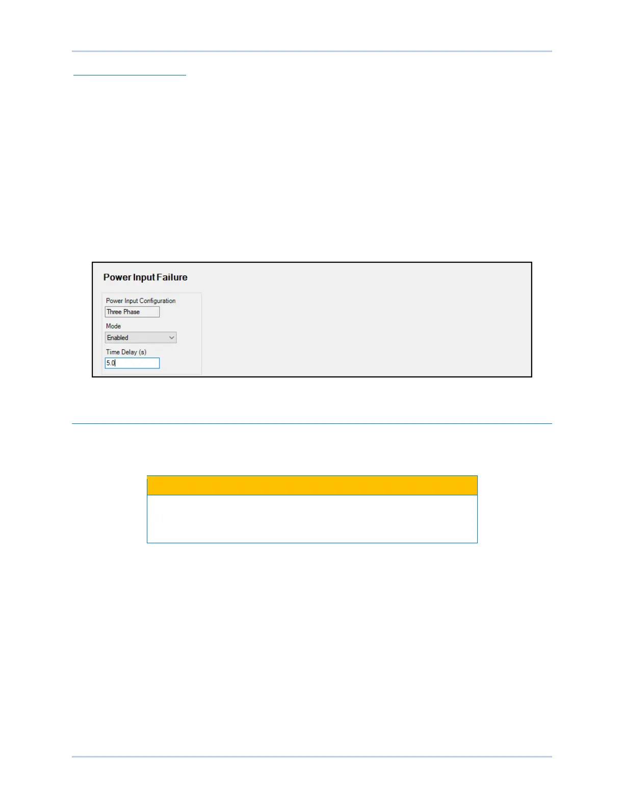
Power input failure protection can be used for PMG applications, shunt-, or PMG-powered systems. This
protection is only active in Start mode and after soft start. A time delay setting delays power input failure
annunciations to accommodate transient reductions/imbalances in the operating power input voltage.
Power input failure protection can be enabled and disabled without altering the time delay setting. The
selected power input configuration is shown as a read-only value. Power input failure pickup and trip
elements in BESTlogicPlus can be used in a logic scheme to initiate corrective action in response to the
condition. BESTCOMSPlus power input failure settings are illustrated in Figure 10-15.
Figure 10-15. Power Input Failure Protection Settings
Sync-Check Protection
BESTCOMSPlus Navigation Path: Settings Explorer, Protection, Sync Check (25)
HMI Navigation Path: Settings, Protection, Sync Check (25)
Because the DECS-250 sync-check and automatic synchronizer
functions share internal circuitry, the sync-check function is not
available when the automatic synchronizer style option is selected.
When enabled, the sync-check (25) function supervises the automatic or manual synchronism of the
controlled generator with a bus/utility. During synchronizing, the 25 function compares the voltage, slip
angle, and slip frequency differences between the generator and bus. When the generator/bus
differences fall within the setting for each parameter, the 25 status virtual output asserts. This virtual
output can be configured (in BESTlogicPlus) to assert a DECS-250 contact output. This contact output
can, in turn, enable the closure of a breaker tying the generator to the bus.
An angle compensation setting is provided to offset phase shift caused by transformers in the system. For
more details on the angle compensation setting, see the Synchronizer chapter.
When the Gen Freq > Bus Freq setting box is checked, the 25 status virtual output will not assert unless
the generator frequency is greater than the bus frequency. Sync-check protection settings are illustrated
in Figure 10-16.