11-10 9440300990
Limiters DECS-250
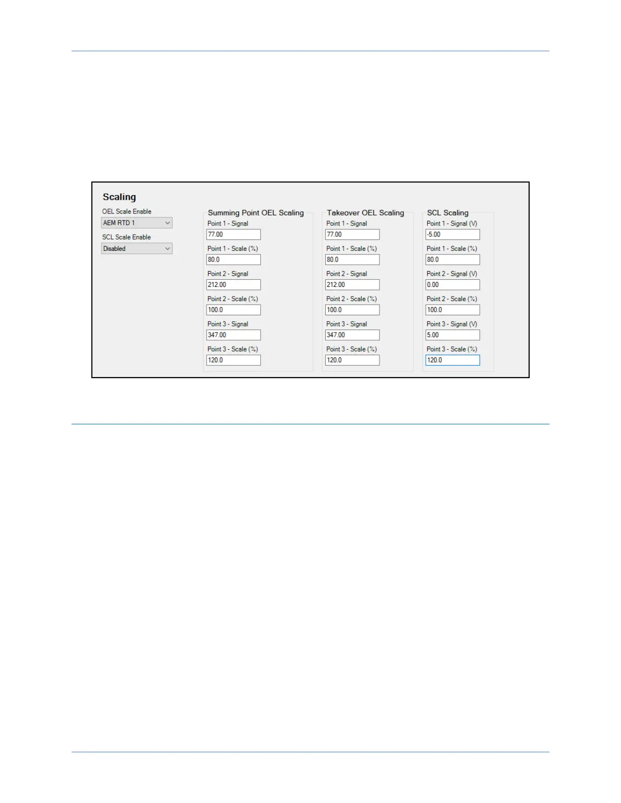
With the scaling input set to Auxiliary Input, the signal value for each point represents the auxiliary control
input. This input can be a 4 to 20 mAdc signal applied to terminals I+ and I– or a –10 to +10 Vdc signal
applied to terminals V+ and V–. (The input type is selected in BESTCOMSPlus). See the Auxiliary Control
chapter of this manual for details.
With the scaling input set to AEM RTD #, the signal value for each point represents an AEM RTD input in
degrees Fahrenheit. See the Analog Expansion Module chapter of the manual for details.
The scale value for each point defines the limiter low level as a percent of rated field current for the OEL
and rated stator current for the SCL.
Figure 11-12. Limiter Scaling Settings
Underfrequency Limiter
BESTCOMSPlus Navigation Path: Settings Explorer, Operating Settings, Limiters, Underfrequency
HMI Navigation Path: Settings, Operating Settings, Limiters, UEL
The underfrequency limiter is selectable for underfrequency limiting or volts per hertz limiting. These
limiters protect the generator from damage due to excessive magnetic flux resulting from low frequency
and/or overvoltage.
Underfrequency and volts per hertz limiter settings are illustrated in Figure 11-15.
If the generator frequency decreases below the corner frequency for the selected underfrequency slope
(Figure 11-13), the DECS-250 adjusts the voltage setpoint so that the generator voltage follows the
underfrequency slope. The adjustment range of the corner frequency and slope settings enables the
DECS-250 to precisely match the operating characteristics of the prime mover and the loads being
applied to the generator.