9440300990 11-11
DECS-250 Limiters
Figure 11-13. Typical Underfrequency Compensation Curve
Volts per Hertz
The volts per hertz limiter prevents the regulation setpoint from exceeding the volts per hertz ratio defined
by the V/Hz High Limiter
D
and V/Hz Low Limiter
E
settings. A typical volts per hertz limiter curve is
illustrated in Figure 11-14.
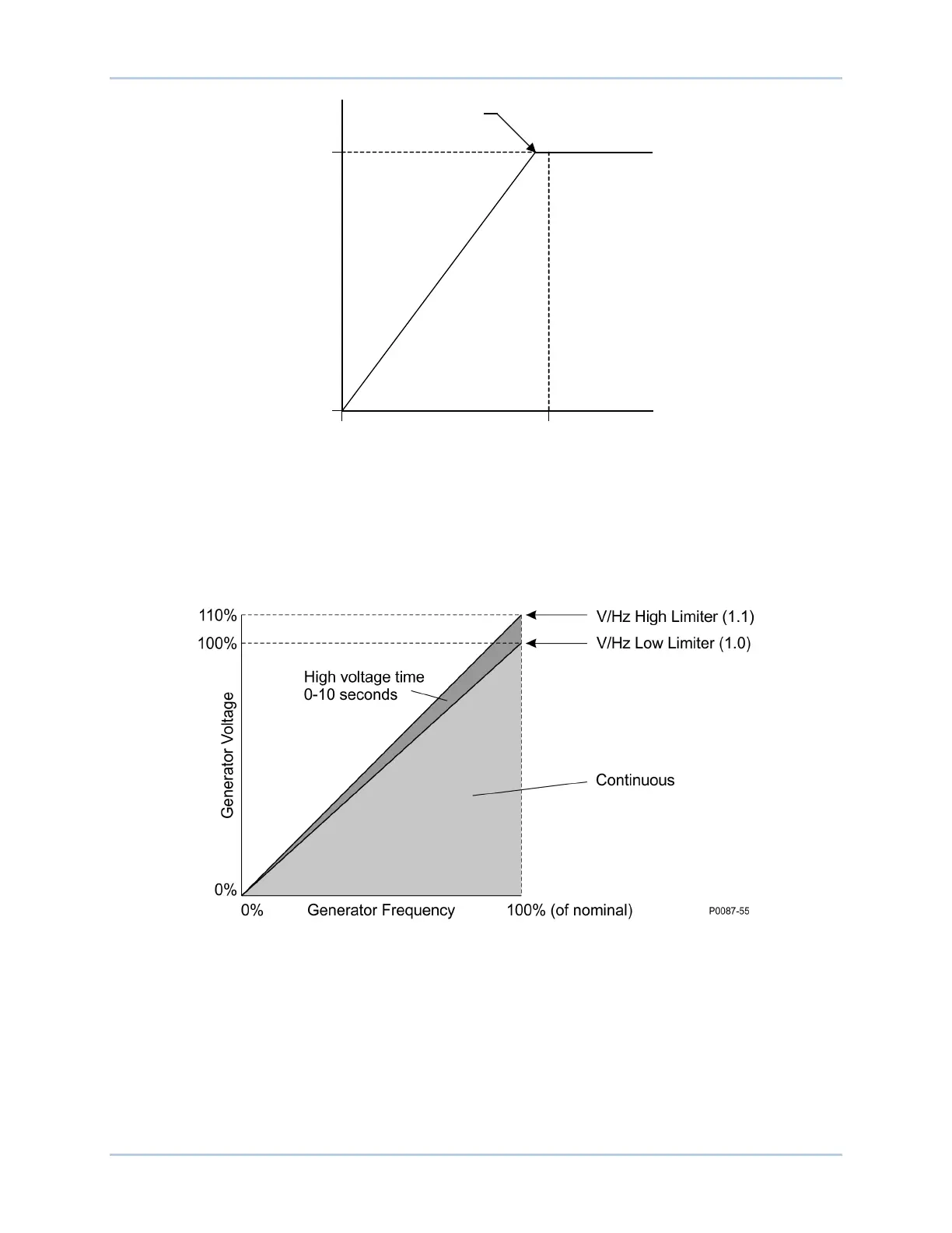
Figure 11-14. Typical 1.1 PU Volts per Hertz Limiter Curve
Volts per hertz limiter operation is established by the V/Hz High Limiter, V/Hz Low Limiter, and V/Hz Time
Limiter settings. The generator may operate continuously at setpoints below the low limit threshold. When
the regulation setpoint is greater than the low limit threshold for the duration of the time delay, the setpoint
is reduced to the low limit threshold and is prevented from exceeding the low limit threshold. The
regulation setpoint is prevented from exceeding the value of the high limit threshold at all times.
Corner Frequency
GENERATOR VOLTS
GENERATOR FREQUENCY
P0004-34.vsd
12-03-01
0 %
100 %
Nominal
10 Hz