12-4 9440300990
Grid Code DECS-250
Active Power Level Selection Settings
When the Active Power Input Source setting is set to Active Power Level Selection, the Active Power
Setpoint setting is not used.
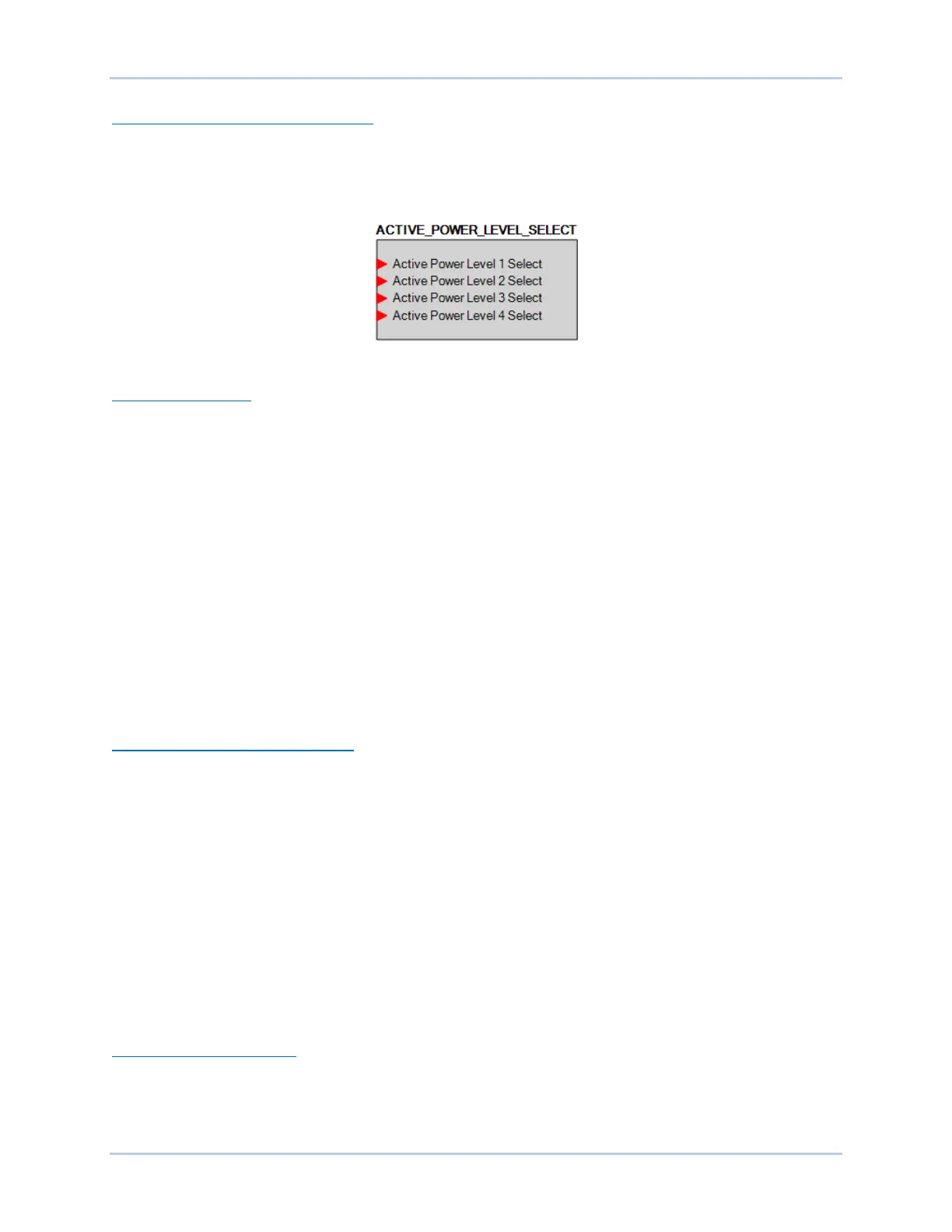
Each of the four Active Power Level settings corresponds to an input on the Active Power Level Select
logic element (Figure 12-3). See the BESTlogicPlus chapter for details.
Figure 12-3. Active Power Level Select Logic Element
Adjustment Sources
The active power setpoint may be adjusted by the DECS-250 auxiliary input, an Analog Expansion
Module AEM-2020 analog input, or via remote communication (Modbus
®
or CAN bus). For all adjustment
sources, the value of the APC Gain setting is applied to the value read from the selected input. Refer to
the CAN Communication and Modbus Communication chapters for more information on adjusting the
setpoint via remote communication.
Auxiliary Input
To use the DECS-250 auxiliary input as the grid code Active Power Control adjustment source, make the
following settings:
• On the Auxiliary Input screen, set the Input Function setting to Grid Code Input. Refer to the
Auxiliary Control chapter for details.
• On the Active Power Control screen, set the Adjust Source setting to Auxiliary Input.
Refer to the Auxiliary Control chapter for details on how the auxiliary voltage (Vaux) is calculated.
Vaux is multiplied by 0.01 and the value of the APC Gain setting:
(APC Adjust = Vaux x 0.01 x APC Gain).
Active Power PI Controller Settings
Gains are established by the Loop Gain (Kg) and Integral Gain (Ki) settings. Maximum and minimum
power output is established by the Max Power Output and Min Power Output settings.
APC Bridging
When APC Bridging is enabled, a third party active power setpoint is inserted directly into the normalized
governor bias where it is scaled by the AEM Gain before going into the speed governor bias input. This
bypasses the DECS-250’s active power control modes.
LFSM
When grid frequency exceeds the dead band threshold, LFSM becomes the active control mode, if
enabled. During over or underfrequency conditions, output power should change as fast as possible to
respond to the change requested by the curve illustrated in Figure 12-4. When frequency is low, the
generating units increase their output power to support the grid. When frequency is high, the generating
units decrease their output power to help prevent grid frequency from rising further.
LFSM Dead Band Settings
The LFSM-U Dead Band setting establishes the deadband minimum frequency and the LFSM-O Dead
Band setting establishes the deadband maximum frequency.