12-6 9440300990
Grid Code DECS-250
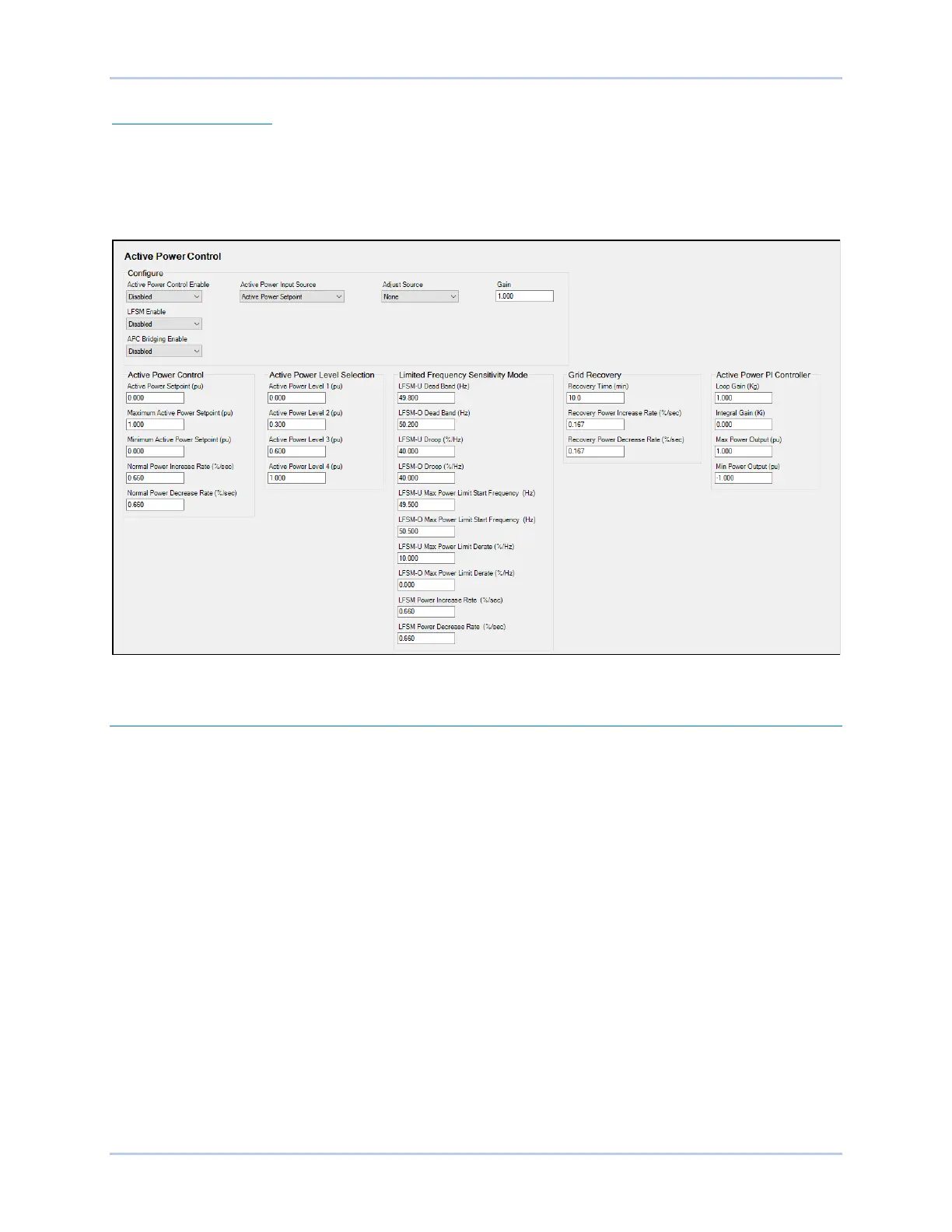
Grid Recovery Settings
The Recovery Time setting establishes the amount of time the grid frequency must remain within the
dead band before the grid is deemed stable and the DECS-250 can return to Active Power Control mode.
Power output ramp rates are established by the Recovery Power Increase Rate and Recovery Power
Decrease Rate settings. These rates are used when Grid Recovery mode is active.
Figure 12-5. Active Power Control
Reactive Power Control
Five reactive power control modes are provided:
1. Reactive power, voltage characteristic – Q(U)
2. Characteristic curve reactive power as a function of the active power – Q(P)
3. Reactive power with voltage limiting function – Q(Voltage Limit)
4. Displacement factor cos. (power factor) – Q(PF)
5. Fixed W reactive power – Q(third party)
If not specified, the default control mode is power factor with a value of 1.0.
Reactive Power Control Time Response
Responses to setpoint changes in LVRT modes Q(U), Q(P), and Q(Voltage Limit) must follow the
characteristic curve illustrated in Figure 12-6. The time constant is established by the PT1 Time Constant
setting. When in Power Factor mode, the time can take up to 60 seconds for settling into the 5%
tolerance band. The Vbus Time Constant setting establishes the time constant for the low-pass filter on
the bus voltage measurement.