12-18 9440300990
Grid Code DECS-250
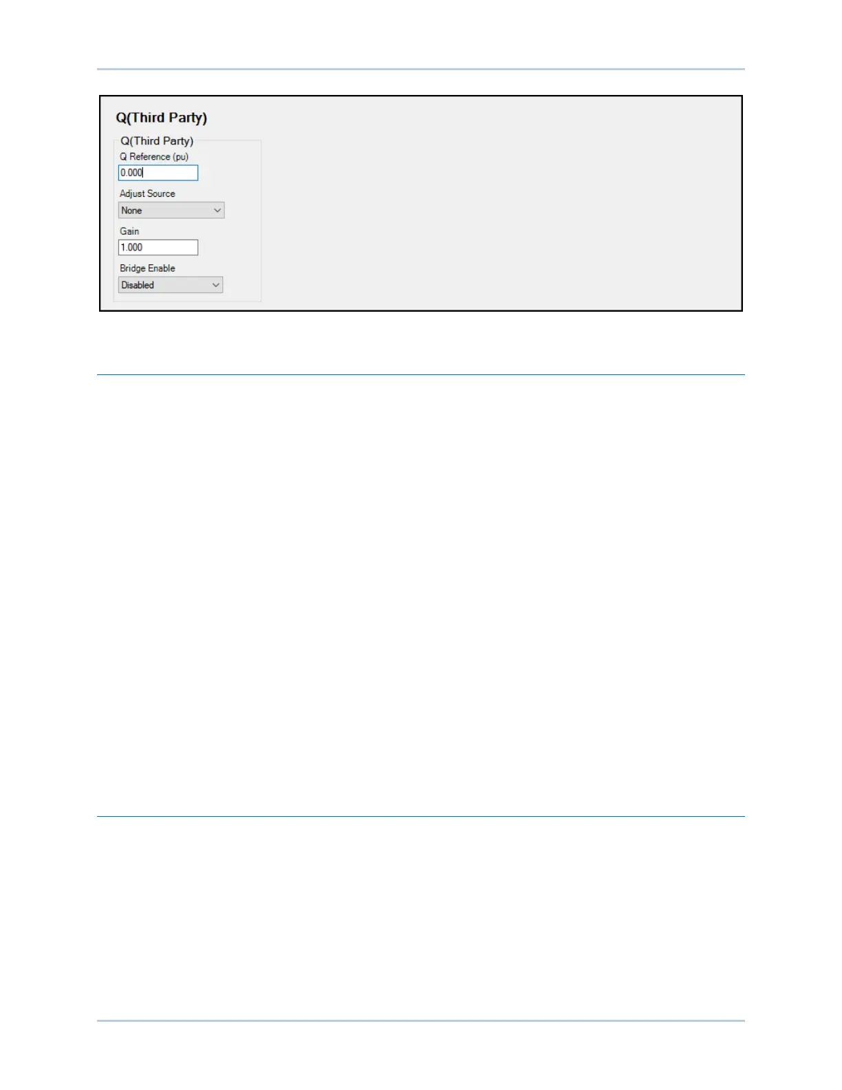
Figure 12-21. Reactive Power Control, Q(Third Party) Screen
Remote Communications
Communication timers are used to assess whether Modbus or CAN bus communications has failed.
There is one timer for Modbus and a separate timer for CAN bus. The timers constantly count and any
time the adjust setting is written, the associated timer is reset to zero. The Failure Time Delay setting is
located on LVRT Configure screen.
If the Modbus timer counts up to the value of the Failure Time Delay setting and the Adjust Source is set
to Modbus, an Active Power Control Remote Communications Failure occurs. The same is true for CAN
bus communication.
If an AEM Comms Failure is detected by the DECS-250 and the Adjust Source is set to an AEM analog
input, an Active Power Control Remote Communications Failure occurs.
Remote Communication Failure
Remote communications failures are recorded in the logs and made available in BESTlogicPlus via the
appropriate APC or LVRT Comm Fail status input. Refer to the BESTlogicPlus chapter for details. A
remote communications failure has no preset effect on APC or LVRT operation. However, the APC or
LVRT Comm Fail status inputs may be used with the Freeze APC Output or Freeze LVRT Output logic
elements to freeze the output of the APC or LVRT PID controllers if desired.
In the event of an LVRT remote communications failure, system behavior is determined by the LVRT
Failure Mode setting. The two modes of operation are:
1. Hold Q Value: When selected, the desired reactive power (Q) level determined by LVRT is
frozen.
2. Q(PF): When selected, the system switches to fixed power factor operation.
Setpoints
Reactive Power Control Mode
In any reactive power control mode, other than Q(P), each setpoint is programmable through a setting or
remote communication. The setpoint can be set through BESTCOMSPlus, the front panel, Modbus, or
CAN bus. In addition, each setpoint may be biased through an analog input in the DECS-250 and in the
AEM-2020 Analog Expansion Module. Loss of remote communications is detected by the DECS-250.
Setpoints are calculated as the sum of the user setting value and an adjustment offset received from
remote communications. In modes Q(U), Q(Voltage Limit), Q(PF), and Q(Third Party), the Adjust Source
setting allows selection of the adjustment source. The selections are: None, Auxiliary Input, Modbus, CAN
bus, or one of eight AEM analog inputs. A Gain setting specifies the gain to be applied to the DECS-250
auxiliary analog input or AEM analog input value to achieve the desired adjustment value.