Manual_ProfibusDPV2_BIDE_EN.docx 9/41 Baumer IVO GmbH & Co. KG
22.11.12 Villingen-Schwenningen, Germany
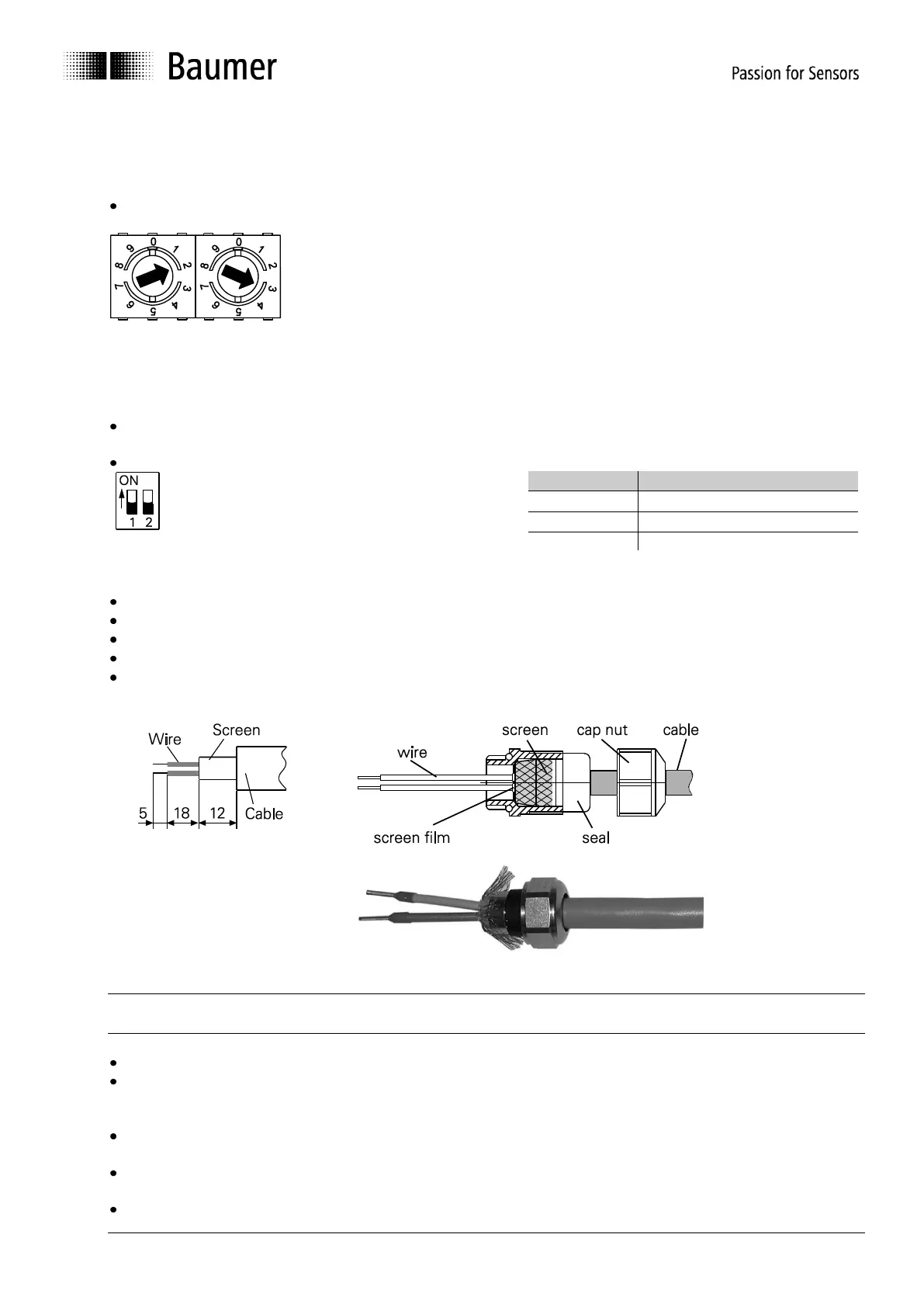
4.2.2. Setting the user address
The user address is set decimally using the two rotary switches provided in the bus cover.
The maximum number of users is 99.
Decimal setting of the user address by the help of rotary switches 1 and 2 (default setting 00).
4.2.3. Terminating resistor
If the encoder is the final device in the bus line it is mandatory to terminate the bus by resistors. The resistors
are integrated in the bus cover and connected by means of a two-pole DIP switch.
The internal terminating resistors must be switched to „ON“ in case of final user by help of the 2-pole DIP
switch (default setting OFF). The two switches must always be set in the same direction.
both ON = final user
both OFF = all other users
4.2.4. Connecting the bus cover
Release the cap nut of the cable gland
Push the cap nut and seal insert with contact sleeve onto the cable sheath.
Strip the cable heath and cores, shorten the shield film where it exists (see fig.)
Bend over the braided shield by approx. 90°.
Push the sealing insert with contact sleeve along as far as the braided shield. Insert the sealing insert
with contact sleeve and cable flush into the cable gland and tighten the cap nut.
Take care that by no means the voltage supply is assigned to bus terminals A/B, this could damage
electronics components in the bus cover.
Avoid stub lines, especially with bus clocks greater than 1.5Mbit/s
Clamps with the same designation are internally connected to each other and identical in functionality.
Maximum load on the internal clamped connections UB-UB and GND-GND is 1 A each.
Signals A and B are decoupled at 100 nH inductivity each.
For voltage supply use cable gland 3 only. For the bus lines, either cable gland 1 or 2 may be used.
Please observe the admissible cable cross-sections.
Guide the cores the shortest way from the cable gland to the terminal connector. Observe the admissible
core-cross sections, use ferrules with flexible cores.
Avoid any crossings of data lines and supply line.