37
13.0 Changing Components
© Baxi Heating UK Ltd 2017
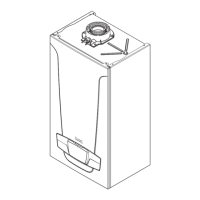
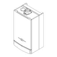
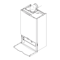
Automatic Air
Vent
Fig. 58
Pump Flow
Pipe
13.10 Pump - Complete (Fig. 58)
1. Disconnect the electrical supply plugs from the pump.
2. Close the flow and return isolation taps and drain the
boiler primary circuit. For ease of access remove the
heating pressure gauge (13.14) & diverter valve motor
(13.19).
3. Undo the three screws securing the body to the inlet
assembly and pump flow pipe. Draw the complete
pump forwards.
4. Remove the automatic air vent and transfer to the
new pump body.
5. Examine the ‘O’ ring seals, replacing if necessary and
reassemble in reverse order.
13.11 Automatic Air Vent (Fig. 58)
1. See Section 13.21 to remove the expansion vessel.
Close the flow and return isolation taps and drain the
primary circuit.
2. The automatic air vent is a bayonet fitting. Remove by
twisting anticlockwise.
3. Fit the new automatic air vent, ensuring the ‘O’ ring is
fitted and the cap is open . Reassemble in reverse order.
Control Box removed
for clarity