3.4 Electrical diagram
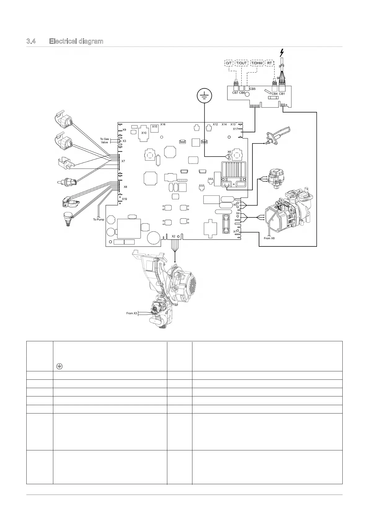
Fig.5 Boiler electrical wiring diagram
3 Technical specifications
Tab.15 Electrical connections
X1
Power supply:
L: Live 230 V – 50 Hz
N: Neutral
: Earthing connector
X2 Fan supply (FAN)
X3 Gas valve (GV)
X4 Pump power supply
X5 3-way valve motor power supply
X6
Earth connections
X7
Sensors:
Limit thermostat (ST)
Installation return temperature (SRT)
Installation flow temperature (SFL)
Flue gas temperature (FS)
X8
Sensors:
DHW flowmeter (HS)
Heating circuit pressure switch (SP)
Pump PWM signal (PWM PUMP)
X9 CAN connection
X10 Service interface
X17 Open Therm room unit (OT)
X17
Outside sensor (OS)
X17
External tank sensor - accessory (BS)
X15 Boiler stoppage (with open contact)
RT
Room thermostat contact (230 V)
18 600 Combi 2