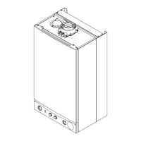
6.4.1 Accessing the electrical connections
Fig.38 Accessing the circuit board
6 Installation
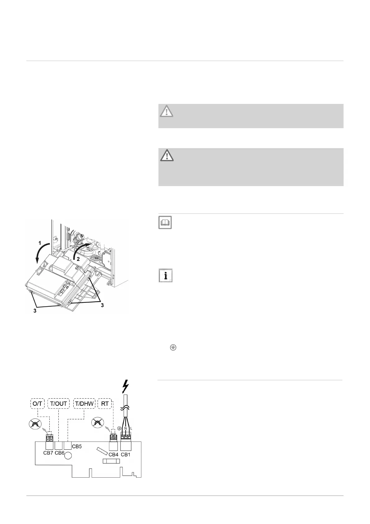
To access the electrical connection board:
Pull the control panel downwards (1).
Lift the rear cover (2).
Release the catches to remove the cover (3).
Important
Do not use excessive force as this could break the plastic hooks.
See
Section 10.3.1 Accessing the boiler components to remove the
front cover
1
2
3
The supply cable is connected to the connection PCB using
the CB1 connection (Fig. 39).
: Earth connection:
6.4.2
Connecting the room thermostat
Before connecting the room thermostat (RT) or Open Therm (OT)
device, remove the link wire on the terminal board as shown in figure 39.
Fig.39 Connecting the room thermostat RT
The connections are as follows:
L: 230 V (brown wire)
N: Neutral (blue cable)
6.4 Electrical connections
The electrical safety of the equipment is only ensured when it is correctly
connected to an effective earthing system in accordance with the
prevailing safety standards for installations. The boiler must be electrically
connected to a 230 V single phase + earth mains supply using the three-
wire cable provided, respecting the Line-Neutral polarity.
Caution
This connection must be made using a two-pole switch with
contact opening of at least 3 mm.
If the power supply cable must be replaced, a harmonised “HAR H05 VV-
F” 3x0.75 mm2 cable with a maximum diameter of 8 mm must be used.
Warning
Check that the total nominal consumption of the accessories
connected to the appliance is less than 1 A. If it is higher, a relay
must be installed between the accessories and the electronic
board.
42 600 Combi 2