6 Installation
6. The pipework must be clipped at suitable intervals to support it, com
mencing as close to the boiler as possible.
6.2.2 Connecting the condensate drain
1. Remove the blanking cap, and using the straight rubber coupling
supplied, connect the condensate drain pipework to the boiler con
densate trap outlet pipe.
See
Ensure the discharge of condensate complies with any national or
local regulations in force (see HHIC recommendations).
See
Condensate drain, page 27.
2. The straight rubber coupling will accept 21.5 mm (
3
/
4
in) plastic
over-flow pipe which should generally discharge internally into the
house-hold drainage system. If this is not possible, discharge into
an out-side drain is acceptable.
Important
The boiler condensate trap should be primed by pouring
approximately 300 ml of water into the flue spigot. Do not allow
any water to fall into the air inlet.
6.3 Air supply/flue gas connections
6.3.1 Connecting the flue/chimney
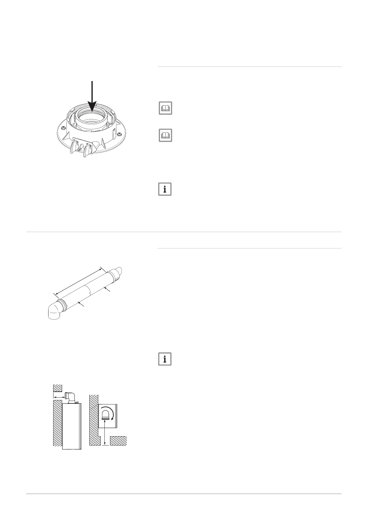
HORIZONTAL TELESCOPIC FLUE (concentric 60/100)
1
2
3
315 mm to 500 mm
Connection assembly
Terminal assembly
There are two telescopic sections, the terminal assembly and the connec-
tion assembly, a roll of sealing tape and two self tapping screws. A 93° el-
bow is also supplied.
The two sections can be adjusted to provide a length between 315 mm
and 500 mm when measured from the flue elbow (there is 40 mm
engagement into the elbow).
1.
2.
3.
Locate the flue elbow on the adaptor at the top of the boiler. Set the
elbow to the required orientation.
Important
The flue elbow is angled at 93° to ensure a fall back to the boiler.
Measure the distance from the outside wall face to the elbow. This
dimension will be known as " X" .
If the distance from the flue elbow to the outside face of the wall is
less than 250 mm the connection assembly can be discarded and
the terminal assembly fitted directly into the elbow.
4. In instances where the dimension " X" is between 250 mm and
315 mm it will be necessary to shorten the terminal assembly by
careful cutting to accommodate walls of these thicknesses.
Fig.33 Pour 300ml of water into flue spigot
PN-0000602
Fig.34 Telescopic flue
PN-0000462
3
1
2
Fig.35 Flue dimension X
PN-0000463
X
X
40 600 Combi 2