5.7 Connecting diagrams
A
B
C
D
E
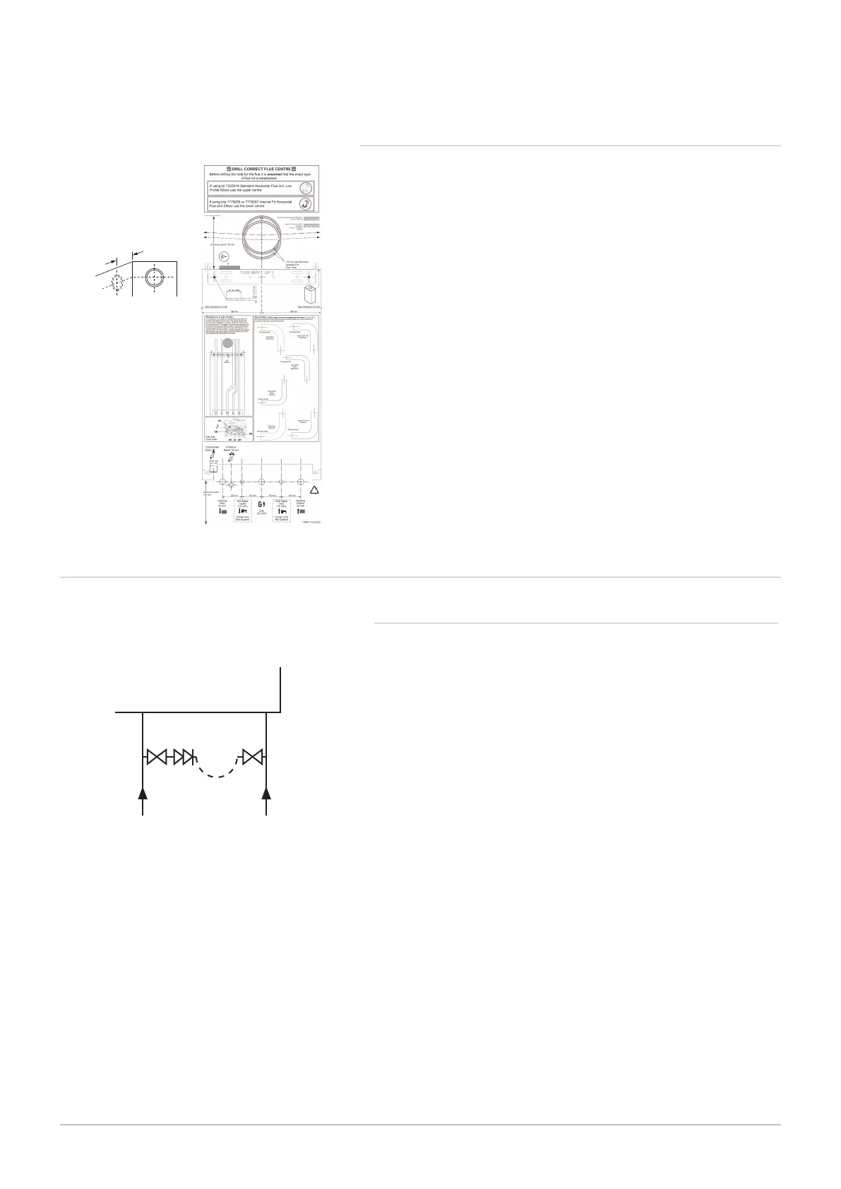
Domestic hot water mains inlet
Central heating return
Stop valve
Double check valve (Not supplied)
Loop (Temporary or Permanent)
A filling point connection on the central heating return pipework must be
provided to facilitate initial filling and pressurising and also any subsequent
water loss replacement/refilling.
The filling method adopted must be in accordance with all relevant water
supply regulations and use approved equipment.
Your attention is drawn to:
for GB: Guidance G24.2 and recommendation R24.2 of the Water Regu
lations Guide.
for IE: the current edition of I.S. 813 Domestic Gas Installations.
A Cold mains in
B Heat return
The sealed primary circuits may be filled or replenished by means of a
temporary connection between the circuit and a supply pipe, provided a
"Listed" double check valve or some other no less effective backflow
prevention device is permanently connected at the inlet to the circuit and
the temporary connection is removed after use.
When the permanent filling link supplied with the boiler is fitted it is not
necessary to remove any part of it after filling or re-pressurising.
Fig.28 System filling circuit
PN-0000347
A
B
C
C
D
E
5 Before installation
37
5.7.1 Filling information
600 Combi 2
5.6.2 Initial preparation
1.
2.
3.
4.
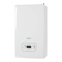
After considering the site requirements position the fixing template
on the wall ensuring it is level both horizontally and vertically.
Mark the position of the two most suitable fixing slots for the wall
bracket.
Mark the position of the centre of the flue hole (rear exit). For side
flue exit, mark as shown.
If required, mark the position of the gas and water pipes. Remove
the template.
5. Cut the hole for the flue (minimum diameter 116 mm).
6.
7.
Drill the wall as previously marked to accept the wall plugs supplied.
Secure the wall bracket using the fixing screws.
Using a spirit level ensure that the bracket is level before finally
tightening the screws.
Fig.27 Template
150 mm