10.4.7
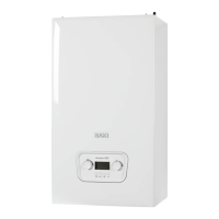
Hall effect sensor
1. Ease the sensor upwards off the hydraulic inlet manifold assembly.
2. Disconnect the electrical plug from the sensor.
3. Connect the plug to the new sensor. Carefully fit the new sensor to
the hydraulic assembly, ensuring it is fully down.
Fig.78 Remove hall effect sensor
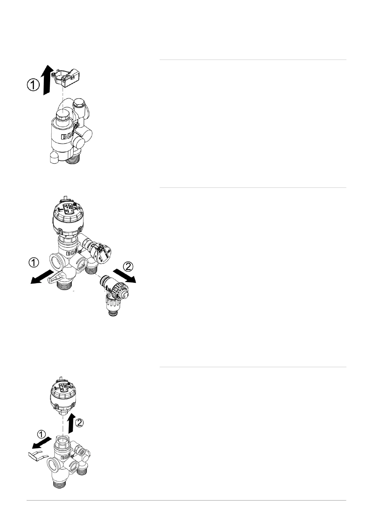
10.4.9 Diverter valve motor
1. Disconnect the multi-pin plug from the diverter valve motor.
2. Hold the motor in place against the spring pressure of the valve as
sembly, remove the securing clip (1).
3. Remove the motor (2).
4. When fitting the new motor it will be necessary to hold the unit firmly
while depressing the valve assembly spring to refit the securing clip.
5. Reconnect the multi-pin plug.
Fig.80 Remove diverter valve
Fig.79 Remove safety pressure relief valve
1. Drain the primary circuit.
2. Disconnect the discharge pipe from the valve and remove the seal
ing grommet.
3. Using a suitable hexagon key undo the grub screw sufficiently to re
lease the valve.
4. Note the orientation of the valve, rotate it and withdraw it from the
manifold.
5. Fit the new valve and ‘O’ ring seal and set to the previously noted
orientation. Tighten the grub screw.
6. Reconnect the discharge pipe ensuring the sealing grommet is in
place to maintain the integrity of the case seal.
10.4.8
Safety pressure relief valve
10 Maintenance
70 600 Combi 2